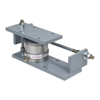
1780-M057-O1 Rev C Hydraulic Floor Stand Tank/Hopper
INSTALLATION, CONT.
Gauging SST Hydraulic Load Cells, Cont.
3. Open Manifold valve number one and pump oil through circuit number one until no air
bubbles are seen coming out of the load cell end of the line.
4. Now remove the plug at the load cell inlet fitting and install the tube.
5. Tighten the tube nut finger tight, then an additional 1/8 to 1/4 turn.
6. Next remove the cap from the bleed port on the cell and attach a plastic bleed hose
placing the end in a clean glass container.
7. Now pump 10 to 12 strokes of oil through the cell to ensure the cell has no trapped air
inside it. If air bubbles are still visible coming from the plastic line continue pumping oil
through the system until no further air remains.
8. Next, remove the plastic bleed tube and replace and snug the bleed port cap. After the
cap is installed stroke the pump one more time and close the manifold valve for cell
number one.
9. See if the three gauge shims are tight in the cell. If not open the bleed valve and pump
another stroke of oil into the cell.
10. Continue this procedure until the shims in the cell are snug.
11. At this point tighten the bleed screw in the manifold.
12. Now carefully open the bleed cap and let a few drops of oil out of the load cell until the
shims can be pulled free and tighten the bleed cap.
13. At this point the cell’s gauge gap, at the tube connection “gauge port” (it is not necessary
to gauge the other two ports) should be very close to the .027 +/- .001 gap that is
necessary for operation.
14. Repeat this procedure on all cells in the system until all cells are bled and filled to the
correct level.
15. Double check the gap after the weighbridge or vessel has been placed on the load cells.
16. Replace the gauge port caps on the cells.

 Loading...