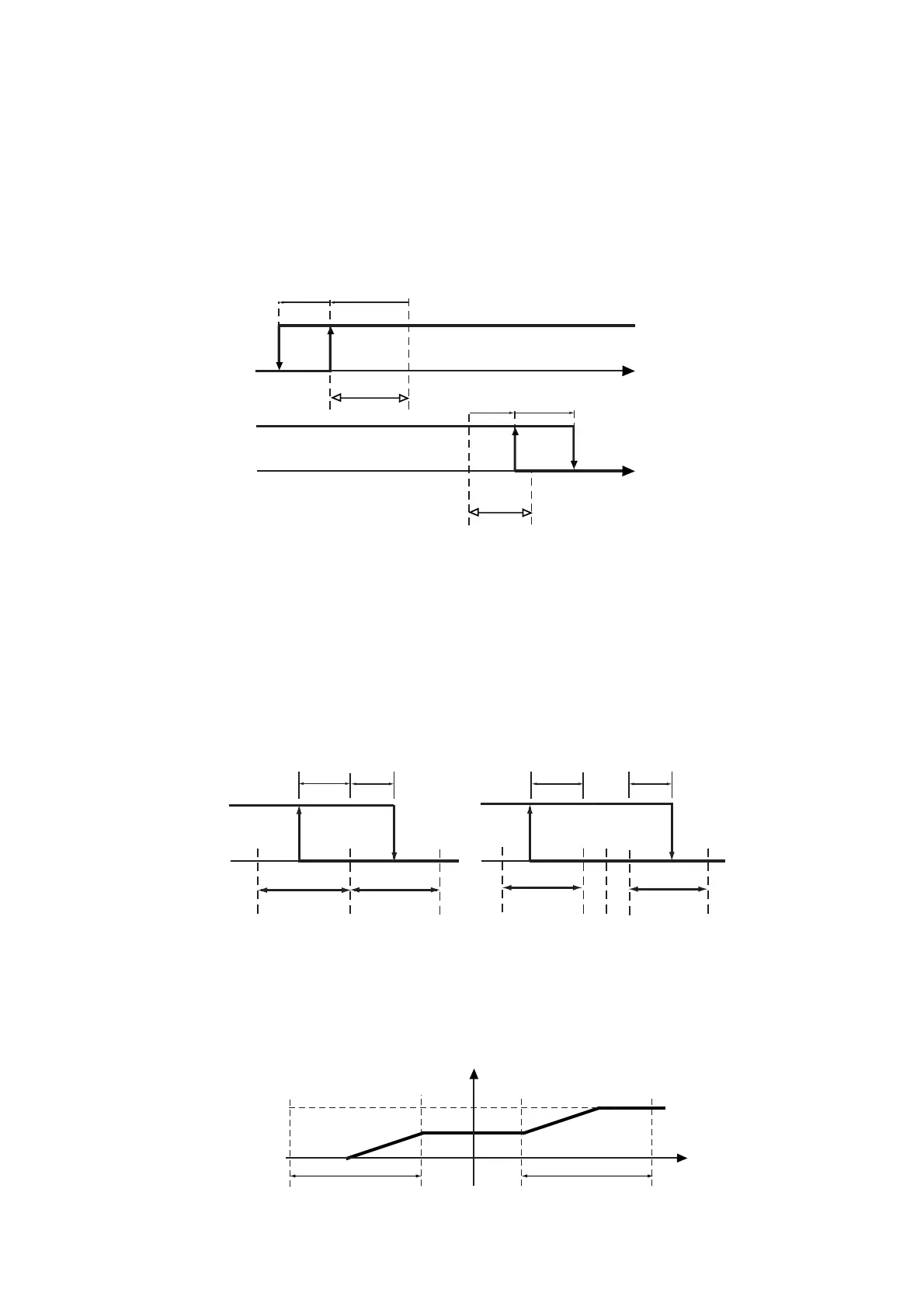
I parametri di funzionamento sono:
St1=10, St2=20, P1=P2=6
OUT1: DIPENDENZA=C34=1, e INSERZIONE=C36= -100
(A), DIFFERENZIALE/LOGICA=C37=+100 (A’)
OUT2: DIPENDENZA=C38=2 e INSERZIONE=C40= +75
(B), DIFFERENZIALE/LOGICA=C41= -50 (B’).
A titolo esemplificativo, vediamo cosa succede alla logica
di regolazione dell’esempio precedente invertendo i valori
di DIFFERENZIALE/LOGICA per le due uscite, ovvero
ponendo C37= -50 e C41=+100. A” e B” sono i nuovi punti
di disinserzione.
8.6 Note integrative al funzionamento speciale
1- Zona neutra P3
Nei Modi 3, 4 e 5 è presente una zona neutra la cui
dimensione è definita da P3. All’interno della zona morta
non possono essere posizionati punti di attivazione o
disattivazione: se questi sono individuati in zone precedenti
e successive al Set lo strumento provvede automaticamente
ad aumentare l’isteresi dell’uscita interessata del valore
doppio di P3. Un esempio è riportato nel disegno sotto-
stante:
- Eventuali uscite PWM (o analogiche) sovrapposte al set
e quindi alla zona Neutra avranno il funzionamento indica-
to in figura. In pratica nella zona neutra l’uscita mantiene
inalterato il livello di attivazione.
Operating parameters:
St1=10, St2=20, P1=P2=6
OUT1: DEPENDENCE=C34=1, ENERGIZATION=C36=
-100 (A), DIFFERENTIAL/LOGIC=C37=+100 (A')
OUT2: DEPENDENCE=C38=2, ENERGIZATION=C40=
+75 (B), DIFFERENTIAL/LOGIC=C41= -50 (B')
Let's analyse what happens by inverting the DIFFEREN-
TIAL/LOGIC values of the two outputs, that is, C37= -50
and C41=+100. A' and B' are the two new disenergization
points.
8.6 Further information on the special mode of
operation
1 - Neutral zone P3:
In Modes 3, 4, 5 there is a neutral zone whose range
depends on the value given to P3. Within the neutral zone
there are no energisation/disenergisation points. In the
event of energisation/disenergisation points beyond the
set-point range, the controller will automatically develop
corrective action, increasing the output hysteresis by two
times of P3 as shown in the graph below:
- In the event of PWM (or analogue) outputs overlaying
the set-point and the neutral zone, the operating logic will
be as follows (within the neutral zone the output maintains
the energization point unchanged):
47

 Loading...