10
ENTER BUTTON
Allows parameter setting (through the and buttons) and is used to confirm
data after setting. (1) If, for example, the display shows a mask with the message:
“Temperature Set-point Setting”, by pressing Enter the cursor will go from 0,0
position to the numeric field where a digit like 020.0 (20 ºC) is displayed. By means
of the
and button it is possible to modify this value. (2) By pressing Enter
again the cursor will go back to 0,0 and at the same time the modified value will be
memorised.
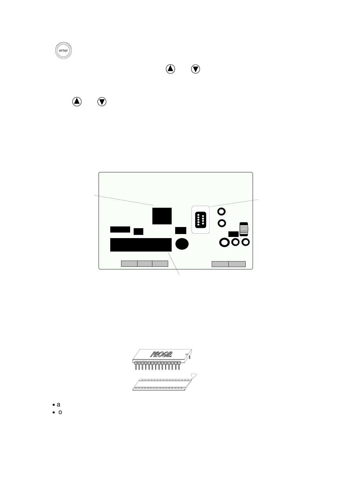
- pCO TERMINAL BOARD REAR PART
The terminal board is composed of
# a section including the microprocessor
# a section which allows interfacing with pCO and a serial printer
MICROPROCESSOR
CONNECTION
CONNECTION
TO pCO
CONTROLLER
TO PRINTER
- EPROM
The Eprom socket is on the interface board.
The Eprom should be placed with the chip reference notches coinciding with the
terminal board ones.
With reference to the picture :
On inserting pay great attention:
an arrow on the label shows the exact Eprom inserting position.
to the Eprom correct polarity, during the set-up the notch on the Eprom should
coincide with the one on the socket.
Particular attention should be paid also to the set-up itself so as to avoid bending or
breaking the component pins.
- TROUBLESHOOTING

 Loading...


