12
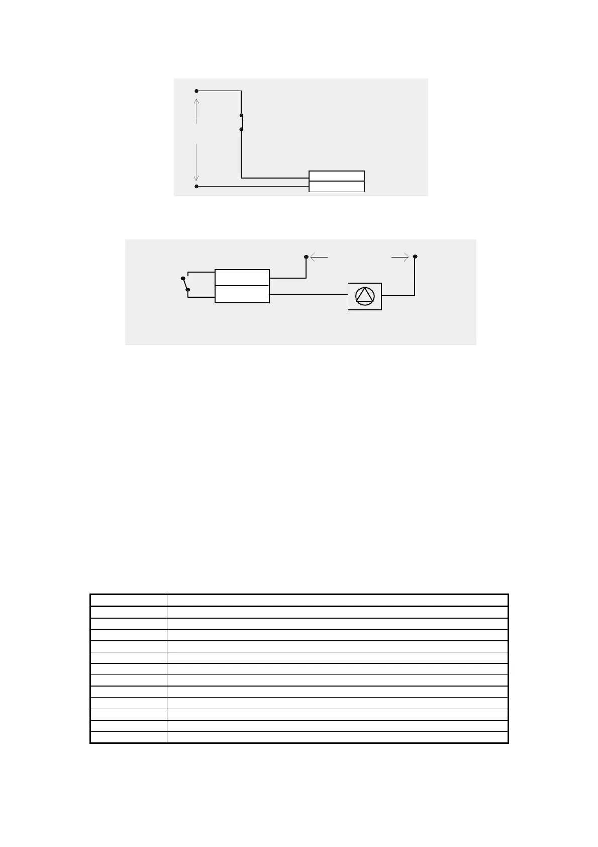
220 Volt
inputs
pCO voltage
ID11R
ID11 (24/220V)
0 Volt = alarm situation
220/24 Volt = normal situation
24 Volt
general alarm
compressor
- DIGITAL OUTPUTS CONNECTION
Macroplus / pCO terminal connector
device (ex. motor pump)
24/220 Volt
1o / NO
1c / C
1.2- HARDWARE: USER INTERFACE
The user interface comprises all those components, such as keypad, display and
LED indicators, which are necessary for the exchange of information between the
user who needs air conditioning and the microprocessor devised by CAREL for the
managing of this operation.
- POWER SUPPLY
Connect the 24 V secondary of the network transformer to inputs G0-G placed on
the controller.
- INPUTS/OUTPUTS
The “Reference” column indicates the contacts on the board shown on page 3.
DIGITAL INPUTS
REFERENCE DIGITAL INPUT
ID1 - IDCM1 COMPRESSOR 1 GENERAL ALARM (HIGH PRESSURE OR OVERLOAD)
ID2 - IDCM1 COMPRESSOR 2 GENERAL ALARM (HIGH PRESSURE OR OVERLOAD)
ID3 - IDCM1 COMPRESSOR 1 LOW PRESSURE
ID4 - IDCM1 COMPRESSOR 2 LOW PRESSURE
ID5 - IDCM1 CLOGGED FILTER
ID6 - IDCM2 FAN OVERLOAD
ID7 - IDCM2 AIR FLOW DETECTOR
ID8 - IDCM2 REMOTE ON / OFF
ID9 - IDCM2 HEATER 1 OVERLOAD
ID10 - IDCM2 HEATER 2 OVERLOAD
ID11 - ID11R NOT USED
ID12 - ID12R FIRE
ANALOGUE INPUTS

 Loading...


