EasyManuals Logo

Carel pCO1 series User Manual

Carel pCO1 series
84 pages
To Next Page IconTo Next Page
To Previous Page IconTo Previous Page
Page #35 background imageLoading...
Page #35 background image
pCO Sistema
Code: +030220336 - rel. 1.5 - 22/12/10
35
4.3.7
4.3.74.3.7
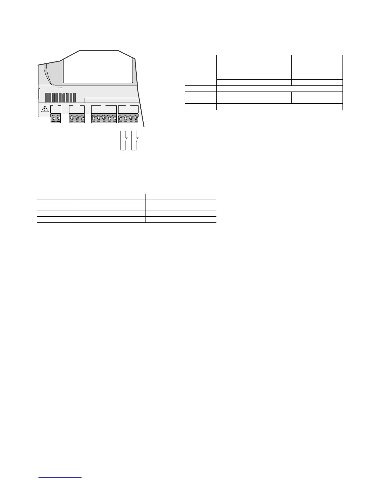
4.3.7 Connecting the analogue inputs selected as ON/OFF
Connecting the analogue inputs selected as ON/OFFConnecting the analogue inputs selected as ON/OFF
Connecting the analogue inputs selected as ON/OFF
A number of analogue inputs on the pCO can be configured as voltage-free digital inputs, not optoisolated.
The inputs must be configured as voltage-free digital inputs by the application program resident in flash memory.
G
G0
+V
term
GND
+5 V
REF
B4
BC4
B5
BC5
J1 J24 J2 J3
field card
input: 24 V / ;50 to60 Hz
max. power:40VA/15W
B4
BC4
B5
BC5
Fig. 4.g
Fig. 4.gFig. 4.g
Fig. 4.g
Warnings:
Warnings: Warnings:
Warnings: the maximum current available at the digital input is 5 mA (thus the rating of the external contact must be at least 5 mA).
4.3.8
4.3.84.3.8
4.3.8 Distance of the analogue inputs
Distance of the analogue inputsDistance of the analogue inputs
Distance of the analogue inputs
The sizes of the cables used for connecting the analogue inputs over a distance are shown in the following table:
type of in
type of intype of in
type of in
put
putput
put
size (mm
size (mmsize (mm
size (mm
2
22
2
) for length up to 50 m
) for length up to 50 m) for length up to 50 m
) for length up to 50 m
size (mm
size (mmsize (mm
size (mm
2
22
2
) for length up to 100 m
) for length up to 100 m) for length up to 100 m
) for length up to 100 m
NTC
0.5
1.0
PT1000
0.75
1.5
I (current)
0.25
0.5
V (voltage)
0.25
0.5
Tab. 4.h
Tab. 4.hTab. 4.h
Tab. 4.h
If the product is installed in industrial environments (application of the EN 61000-6-2 standard) the length of the connections must be less than 30m.
In any case, this length should not be exceeded so as to prevent measurement errors.
Controller
ControllerController
Controller
pCO terminals
pCO terminalspCO terminals
pCO terminals
Digital input wire
Digital input wireDigital input wire
Digital input wire
pCO
pCOpCO
pCO
3
33
3
digit 1 digit 2 digit 3 digit4
BC4 BC5 BC9 BC10
1
11
1
B4 B5 B9 B10
2
22
2
pCO
pCOpCO
pCO
xs
xsxs
xs
Not available
pCO
pCOpCO
pCO
1
11
1
B5 B6
GND GND
1
11
1
2
22
2
pCO
pCOpCO
pCO
C
CC
C
Not available
Tab. 4.g
Tab. 4.gTab. 4.g
Tab. 4.g

Table of Contents

Other manuals for Carel pCO1 series

Questions and Answers:

Question and Answer IconNeed help?

Do you have a question about the Carel pCO1 series and is the answer not in the manual?

Carel pCO1 series Specifications

General IconGeneral
BrandCarel
ModelpCO1 series
CategoryController
LanguageEnglish

Related product manuals