pCO Sistema
Code: +030220336 - rel. 1.5 - 22/12/10
58
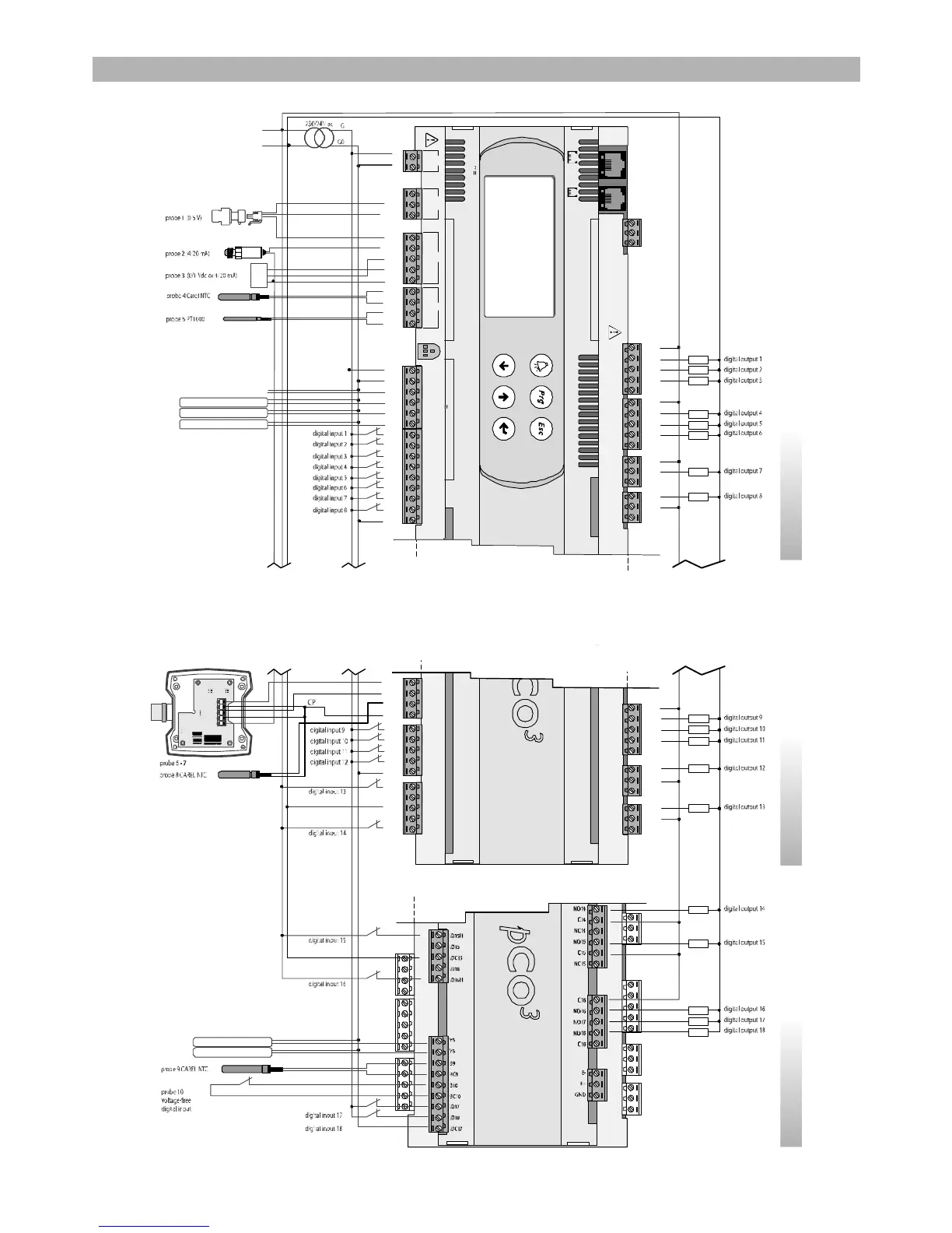
8. GENERAL CONNECTION DIAGRAMS
pCO
pCOpCO
pCO
3
33
3
M
OUT
+V
analog output 1 (0/10Vdc)
analog output 2 (0/10Vdc)
analog output 3 (0/10Vdc)
analog output 4 (0/10Vdc)
analog output 5 (0/10 Vdc)
L
N
analog output 6 (0/10 Vdc)
service card
Rx-/Tx-
Rx+/Tx+
GND
C1
NO1
NO2
NO3
C1
C4
NO4
NO5
NO6
C4
C7
NO7
C7
NO8
C8
NC8
G
G0
B1
B2
B3
GND
+VDC
+Vterm
GND
+5 VREF
B4
BC4
B5
BC5
VG
VG0
Y1
Y2
Y3
Y4
ID1
ID2
ID3
ID4
ID5
ID6
ID7
ID8
IDC1
J1 J24 J2 J3
J10J9
field card serial card
input: 24 V / ;50 to60 Hz
max. power:40 VA/15W
out H
M
N TC
N TC
+ (G)
NO12
C12
NC12
NO13
C13
NC13
C9
NO9
NO10
NO11
C9
B6
B7
B8
GND
ID9
ID10
ID11
ID12
IDC9
ID13H
ID13
IDC13
ID14
ID14H
SMALL MEDIUM LARGE
Fig. 8.a
Fig. 8.aFig. 8.a
Fig. 8.a
 Loading...


