S&2ð
cod. Carel +030221826 rel. 2.0 dated 03/10/02
7
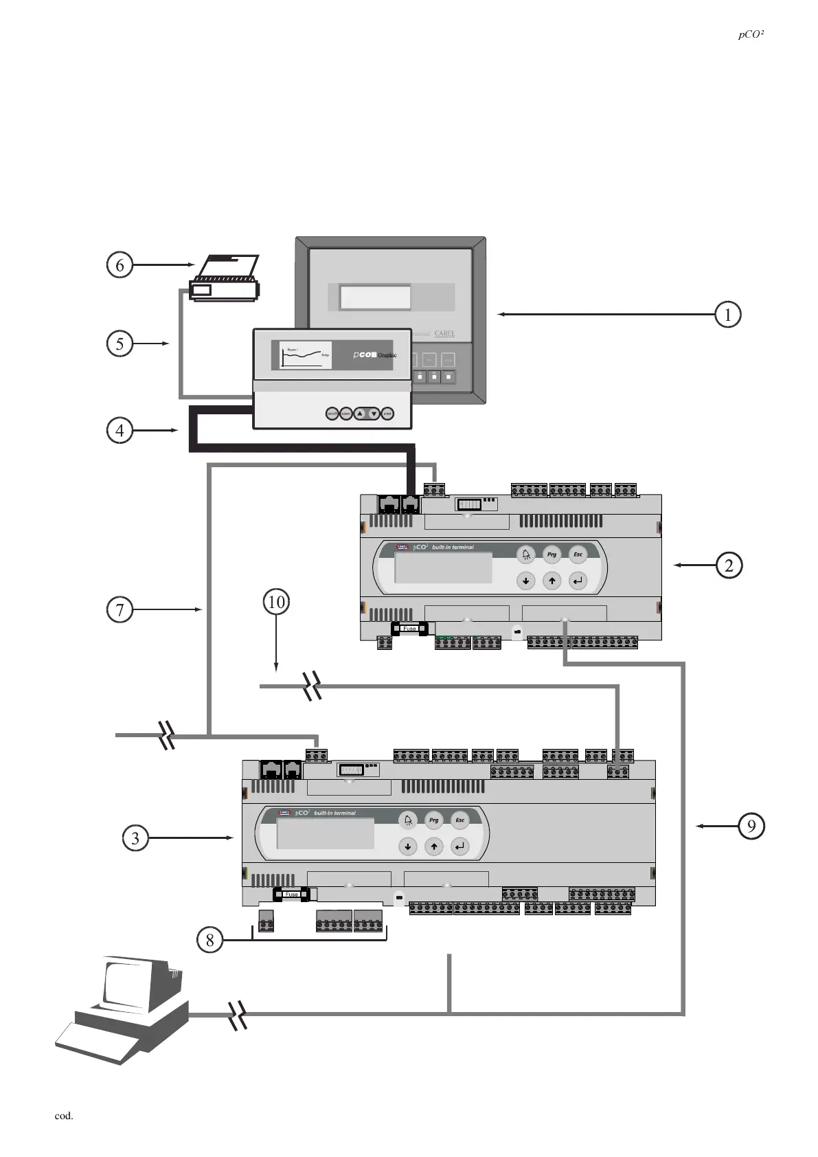
The hardware structure is defined as follows:
1. user terminal with keypad, display and LED signals;
2. pCO
2
(SMALL version);
3. pCO
2
(LARGE version);
4. connecting cable between terminal and pCO
2
;
5. connecting cable between terminal and serial printer (provided by customer);
6. serial printer (provided by customer);
7. AWG20/22 cable for pLAN connection between a series of pCO
2
boards;
8. connection terminal kit (in this case disconnected from the board to make them completely visible);
9. connection to supervisory systems;
10. connection to I/O expansions (LARGE version only).
)LJ
 Loading...


