Do you have a question about the Carel pCO2 and is the answer not in the manual?
Instructions for mounting the pCO2 controller onto a DIN rail, including removal.
Details on power supply requirements, voltage, current, and LED indicators for the pCO2.
Precautions for selecting installation environments and guidelines for correct electrical connections.
Guide to connecting various analogue sensors (NTC, PT1000, voltage, current) to the pCO2 inputs.
Guide for connecting digital inputs to the pCO2, covering 24Vac, 24Vdc, and 230Vac power options.
Instructions for connecting analogue outputs (0/10V) to the pCO2 controller.
Guide for connecting digital outputs (relay and SSR) to the pCO2 controller.
Procedures for installing pCOT and pCOI terminals, including wall/panel mounting and electrical connections.
Detailed electrical specifications for pCO2 controllers, covering CPU, memory, inputs, and outputs.
Instructions and diagrams for panel mounting PCOT* and PCOI* terminals.
Procedure for wall mounting terminals using a bracket and switchbox.
Checks to perform when the unit fails to power on, focusing on power supply and fuse.
Troubleshooting steps for incorrect readings from input signals, including probe and power supply checks.
Troubleshooting steps for humidity (0/1V) and pressure probes, including signal checks and software settings.
Addresses Watch-dog mode, supervisor connection failures, and locked user terminals.
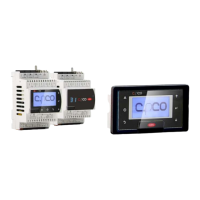
| Model | pCO2 |
|---|---|
| Type | CO2 Controller |
| Protection Rating | IP20 |
| Display | LCD |
| Input Voltage | 24 VAC/VDC ±10% |
| Communication Protocols | Modbus RTU |
| CO2 Measurement Range | 0 to 2000 ppm |