4.9 Installazione dell’EPROM di programma del
terminale con display grafico
Prima di inserire/rimuovere la EPROM togliere l’alimentazione del
terminale con display grafico.
Per un corretto funzionamento del sistema, la EPROM deve essere
inserita nell’apposito zoccolo sulla scheda facendo attenzione che la
tacca sulla superficie della EPROM sia nella direzione della tacca
di riferimento serigrafata sulla scheda. Il programma può essere
memorizzato su due diversi tipi di EPROM in funzione della sua
occupazione di memoria. La più comunemente utilizzata nel caso del
terminale con display grafico, è quella riportata in Tab. 4.9.1.
tipo di EPROM capacità dimensioni
27C1001 128 kByte 32 piedini
Tab. 4.9.1
Tutte le informazioni relative alla gestione del display grafico (font,
grafici e simbologie varie da visualizzare) sono realizzate da un
programma applicativo contenuto in una EPROM. Per installare la
EPROM togliere la scheda schermo o la scheda stampante opzionale
seriale (qualora presente) svitando le relative viti; montare quindi la
EPROM prestando attenzione che la tacca di riferimento sia
posizionata nella stessa direzione di quella indicata dalla serigrafia
della EPROM (rifer.to t.r. Fig. 4.9.1).
Prestare estrema attenzione nel maneggiare questo componente,
tenendo presente quanto segue:
1. rimuovere la scheda che funge da schermo o l’eventuale scheda
opzionale stampante (durante l'installazione della EPROM, prestare
attenzione a non toccare i componenti SMD montati sulla scheda
nello spazio interno allo zoccolo);
2. se eventualmente già presente, per togliere la EPROM dallo
zoccolo, servirsi di un piccolo cacciavite avendo cura di non
rovinare le piste del circuito stampato o qualche altro
componente contiguo;
3. prima di toccare la EPROM, toccare una messa a terra per
scaricare l’eventuale energia elettrostatica accumulata (assicurarsi
di non toccare altri apparecchi sotto tensione);
4. inserire la EPROM sul relativo zoccolo presente sulla scheda,
controllando che tutti i piedini siano inseriti correttamente nelle loro
sedi (esatta corrispondenza tra piedini e loro sedi ed inoltre: non
piegare i piedini ed inserirli con cura nell’apposito zoccolo presente
sulla scheda, tenendo il componente per le estremità prive di piedini);
5. una volta inserita l’EPROM rimontare la scheda che funge da
schermo o l’eventuale scheda opzionale stampante prima di
chiudere il coperchio e rimettere in funzione il terminale.
AVVERTENZA IMPORTANTE: le operazioni di inserzione e
disinserzione della EPROM dallo zoccolo vanno sempre effettuate a
terminale non alimentato.
4.9 Installing the program EPROM in the terminal with
graphic display
Before inserting/removing the EPROM disconnect the power supply to
the terminal with graphic display.
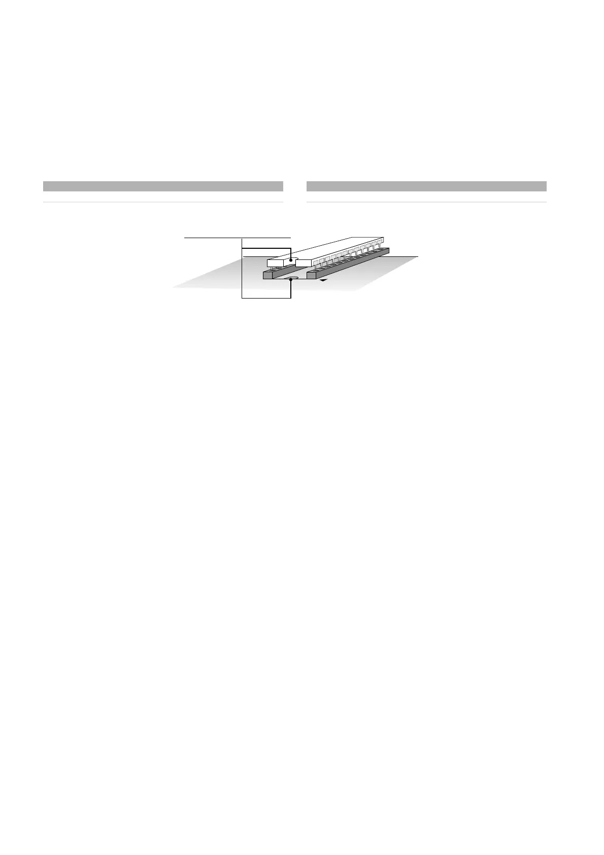
For correct system operation, the EPROM has to be inserted in the
special socket on the board, making sure that the notch on the
surface of the EPROM matches the reference notch silk-screened
on the board.The program can be saved to two different types of
EPROM, according to the its memory requirements.The more
commonly used in the case of the terminal with graphic display is
outlined in Tab. 4.9.1.
type of EPROM capacity size
27C1001 128 kByte 32 pin
Tab. 4.9.1
All the information relating to the management of the graphic display
(fonts, graphs and various symbols displayed) are created by the
application software contained in an EPROM.To install the EPROM
remove the board shield (see Fig. 4.9.1) or the optional serial printer
board (if present), removing the relative screws; then mount the
EPROM, making sure that the reference notch matches the notch
silk-screened on the EPROM. (ref. t.r. Fig. 4.9.1).
Be extremely careful when handling this component, keeping the
following in mind:
1. remove the board which acts as a shield or if necessary the
optional printer board (when installing the EPROM, be careful not
to touch the SMD components on the board in the space inside
the socket);
2. if already present, to remove the EPROM from the socket, use a
small screwdriver being careful not to damage the tracks on the
printed circuit or any other associated component;
3. before touching the EPROM, touch a grounded part to discharge
the necessary static electricity accumulated (do not touch any
powered devices);
4. insert the EPROM in the relative socket on the board, checking that
all the pins are inserted correctly in place (exact correspondence
between the pins and the slots; furthermore, do not bend the pins,
carefully inserting them into the socket, holding the component by
opposite end to the pins);
5. Once the EPROM has been inserted remount the board which acts
a shield or if necessary the optional printer board, before closing
the cover, and place the terminal in operation.
IMPORTANT WARNING: the EPROM must be inserted/removed from
the socket only when the terminal is off.
34
pCO
2
- cod. +030221835 rel. 3.0 - 18.02.03
 Loading...


