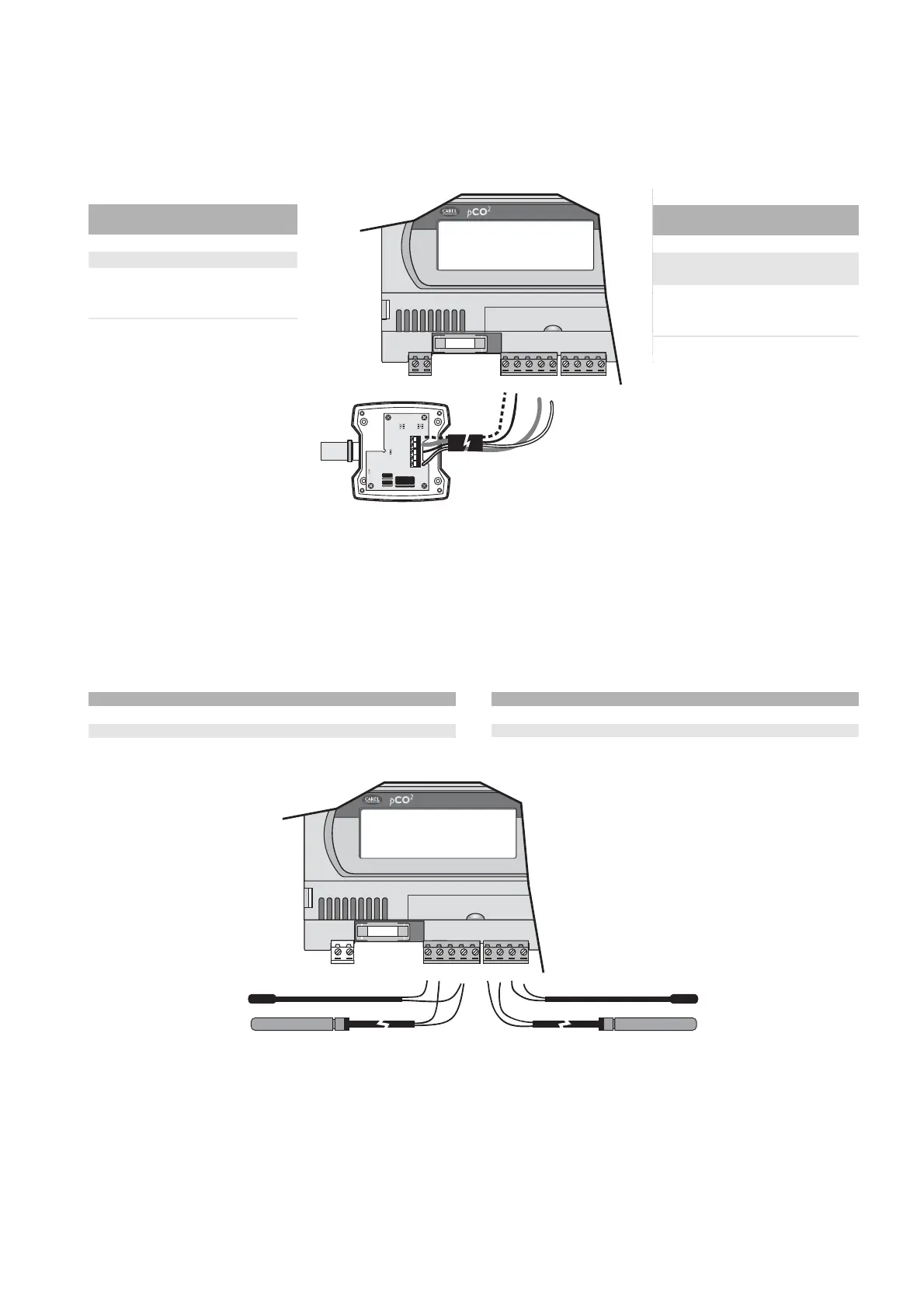
4.4.1 Collegamento sonde attive di temperatura ed umidità
Al pCO
2
possono essere collegate tutte le sonde attive di temperatura
ed umidità della serie AS*
2
Carel configurate come 0/1 V oppure come
4/20 mA. Gli ingressi che possono accettare questi sensori sono: B1,
B2, B3, B6, B7, B8. Gli ingressi devono essere pre-configurati per
segnali 0/1 V o 4/20 mA dal programma applicativo residente nella
flash memory. Di seguito viene illustrato lo schema di collegamento:
morsetti morsetti
pCO
2
sonda descrizione
GND M riferimento
+Vdc +(G) alimentazione
B1, B2, out H, ingressi sonde
B3, B6, ntc universali
B7, B8
Tab. 4.4.1.1
2
per ulteriori dettagli sulle sonde attive
della serie AS* consultare il manuale
tecnico codice: +030221275.
4.4.2 Collegamento delle sonde di temperatura NTC universali
Tutti gli ingressi analogici da B1 a B10 sono compatibili con sensori
NTC a 2 cavi. Gli ingressi devono essere pre-configurati per segnali
tipo NTC dal programma applicativo residente nella flash memory. Di
seguito viene illustrato lo schema di collegamento:
morsetti pCO
2
cavetto sonda NTC
GND, BC4, BC5, BC9, BC10 1
B1, B2, B3, B4, B5, B6, B7, B8, B9, B10 2
Tab. 4.4.2.1
AVVERTENZA: i due cavi delle sonde NTC sono equivalenti in quanto
non hanno polarità, pertanto non è necessario rispettare un ordine
particolare nel collegamento alla morsettiera.
4.4.1 Connecting active temperature and humidity probes
The pCO
2
can be connected to all the Carel series AS*
2
active
temperature and humidity probes configured as 0/1V or 4/20mA.The
inputs which can accept these sensors are: B1, B2, B3, B6, B7, B8.
The inputs must be pre-configured for 0/1V or 4/20mA signals by the
application software resident in the flash memory.The following shows
the connection diagram:
pCO
2
probe
terminals terminals description
GND M reference
+Vdc +(G) power
supply
B1, B2, out H, universal
B3, B4, ntc probe inputs
B5, B6
Tab. 4.4.1.1
2
for further details on the series AS*
active probes refer to the technical
manual, code: +030221275.
4.4.2 Connecting the universal NTC temperature probes
The analogue inputs from B1 to B10 are compatible with 2-lead NTC
sensors.The inputs must be pre-configured for NTC signals by the
application software resident in the flash memory.The following shows
the connection diagram:
pCO
2
terminals NTC probe lead
GND, BC4, BC5, BC9, BC10 1
B1, B2, B3, B4, B5, B6, B9, B10 2
Tab. 4.4.2.1
NOTE: the two NTC probe leads are the same, in that they have no
polarity; therefore it is not necessary to respect any specific order when
connecting to the terminal block.
25
pCO
2
- cod. +030221835 rel. 3.0 - 18.02.03

 Loading...


