4.3 Avvertenze per l’installazione - ambienti di
destinazione e collegamento
Evitare il montaggio delle schede negli ambienti che presentino le
seguenti caratteristiche:
•umidità relativa maggiore del 90%;
•forti vibrazioni o urti;
• esposizioni a continui getti d'acqua;
• esposizione ad atmosfere aggressive ed inquinanti (es.: gas solforici
e ammoniacali, nebbie saline, fumi) con conseguente corrosione e/o
ossidazione;
•elevate interferenze magnetiche e/o radiofrequenze (evitare quindi
l'installazione delle macchine vicino ad antenne trasmittenti);
• esposizioni del pCO
2
all'irraggiamento solare diretto e agli agenti
atmosferici in genere;
•ampie e rapide fluttuazioni della temperatura ambiente;
•ambienti ove sono presenti esplosivi o miscele di gas infiammabili;
• esposizione alla polvere (formazione di patina corrosiva con possibile
ossidazione e riduzione dell'isolamento);
Per il collegamento è indispensabile seguire le segg. avvertenze:
•tensione di alimentazione elettrica diversa da quella prescritta può
danneggiare seriamente il sistema;
•utilizzare capicorda adatti per i morsetti in uso. Allentare ciascuna vite
ed inserirvi i capicorda, quindi serrare le viti. Ad operazione ultimata
tirare leggermente i cavi per verificarne il corretto serraggio;
• separare quanto più possibile i cavi dei segnali delle sonde e degli
ingressi digitali dai cavi dei carichi induttivi e di potenza per evitare
possibili disturbi elettromagnetici. Non inserire mai nelle stesse
canaline (comprese quelle dei cavi elettrici) cavi di potenza e i cavi
delle sonde. Evitare che i cavi delle sonde siano installati nelle
immediate vicinanze di dispositivi di potenza (contattori, dispositivi
magnetotermici o altro);
•ridurre il più possibile il percorso dei cavi dei sensori ed evitare che
compiano percorsi a spirale che racchiudano dispositivi di potenza. Il
collegamento delle sonde deve essere costituito da cavi schermati
(sezione minima per ciascun conduttore: 0,5 mm
2
);
•evitare di avvicinarsi con le dita i componenti elettronici montati sulle
schede per evitare scariche elettrostatiche (estremamente dannose)
dall’operatore verso i componenti stessi;
• qualora il secondario del trasformatore di alimentazione sia posto a
terra, verificare che lo stesso conduttore di terra corrisponda al
conduttore che arriva al controllore ed entra nel morsetto G0;
• separare l’alimentazione delle uscite digitali dall’alimentazione del
pCO
2
;
• non fissare i cavi ai morsetti premendo con eccessiva forza il
cacciavite per evitare di danneggiare il pCO
2
.
4.4 Collegamento degli ingressi analogici
Gli ingressi analogici del pCO
2
sono configurabili per i più diffusi
sensori presenti sul mercato: NTC, PT1000, 0/1 V, 0/10 V, 0/20 mA,
4/20 mA. La scelta tra i diversi tipi di sensori può essere effettuata
selezionando un parametro nel terminale utente (se previsto dal
programma applicativo).
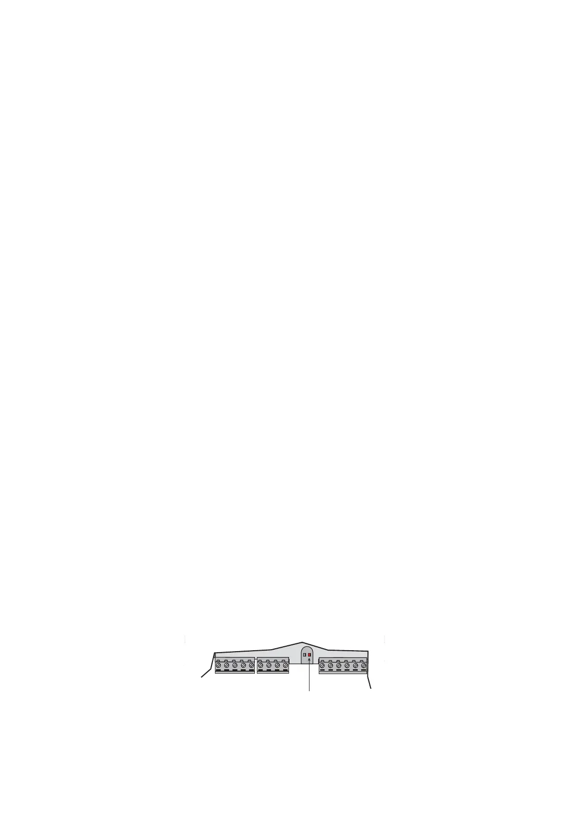
AVVERTENZA: per l’alimentazione delle
sonde attive, è possibile utilizzare i 21 Vdc
disponibili al morsetto +VDC, la corrente
massima erogabile è di 200 mA protetta
termicamente contro i cortocircuiti. La
segnalazione di questa eventualità è
rappresentata dall'accensione del LED
rosso di destra (vedi fig. 4.4.1).
4.3 Installation warnings - destination and connection
environments
Avoid mounting of the boards in environments with the following
characteristics:
•relative humidity over 90%;
•strong vibrations or bumps;
•exposure to continuous jets of water;
•exposure to aggressive and polluting environments (e.g.: sulphuric
and ammoniac gases, saline mists, fumes) with consequent corrosion
and/or oxidation;
•high levels of magnetic and/or radio-frequency interference (thus
avoid installing the machine near transmitting antennae);
•exposure of the pCO
2
to direct sunlight and atmospheric agents in
general;
•large and rapid fluctuations in ambient temperature;
•environments where explosives or inflammable gases are present;
•exposure to dust (formation of corrosive patina with possible oxidation
and reduction of insulation);
The following warnings must be respected for correct connection:
•electrical power supply different from that specified can seriously
damage the system;
•use cable plugs suitable for the terminals being used. Loosen each
screw and insert the cable plug, then tighten the screws. At the end
of the operation lightly tug the cables to check that they are tight;
• separate as much as possible the probe signal and digital input
cables from the inductive load and power cables, to avoid possible
electromagnetic disturbance. Never use the same channelling
(including that used for the electrical cables) for the power cables and
probe cables. Avoid the probe cables being installed in the immediate
vicinity of power devices (contactors, circuit breakers or others);
•reduce the length of the sensor cables where possible and avoid
spiralling around power devices.The probe connection must be made
using shielded cables (minimum cross-section for each lead: 0.5 mm
2
);
•avoid touching or nearly-touching the electronic components on the
boards, to avoid (extremely dangerous) electrostatic discharges from
the user to the components;
• if the power supply transformer secondary is earthed, check that the
ground wire corresponds to the lead which goes to the control and
enters terminal G0;
• separate the power supply to the digital outputs from the power
supply to the pCO
2
;
• do not fasten the cables to the terminals by pressing the screwdriver
with excessive force, to avoid damaging the pCO
2
.
4.4 Connecting the analogue inputs
The pCO
2
analogue inputs can be configured for the more common
sensors on the market: NTC, PT1000, 0/1V, 0/10V, 0/20mA, 4/20mA.
The different types of sensors can be selected via a parameter in the
user terminal (if featured in the application software).
NOTE: the 21Vdc available at the +VDC
terminal can be used for the power supply
to the active probes, the maximum current
being 200mA, protected by circuit-breaker
against short-circuits.The activation of the
latter is signalled by the switching on of the
red LED on the right (see Fig. 4.4.1).
24
pCO
2
- cod. +030221835 rel. 3.0 - 18.02.03

 Loading...


