5.1 Indirizzamento pCO
2
L'indirizzo è impostabile nel range 1-31 utilizzando i dip-switch 1-5. Il
valore dell'indirizzo si ottiene tramite la Tab. 5.1.1.
pesi 124816
indir. sw1 sw2 sw3 sw4 sw5 sw6*
0 senza collegamento alla rete pLAN
1ONOFFOFFOFFOFF -
2OFFONOFFOFFOFF -
3ONONOFFOFF OFF -
4OFFOFFONOFFOFF -
.... .... .... .... .... .... …. stati
.... .... .... .... .... .... …. ON 1
31 ON ON ON ON ON - OFF 0
Tab. 5.1.1
Formula:
indir. =p(SW1)+p(SW2)+p(SW3)+p(SW4)+p(SW5);
esempio applicativo - predisposizione di addr. 19:
19=1+2+16= p(SW1)+p(SW2)+p(SW5).
*AVVERTENZA: il dip-switch n. 6 del pCO
2
non è collegato e quindi la
sua posizione è ininfluente.
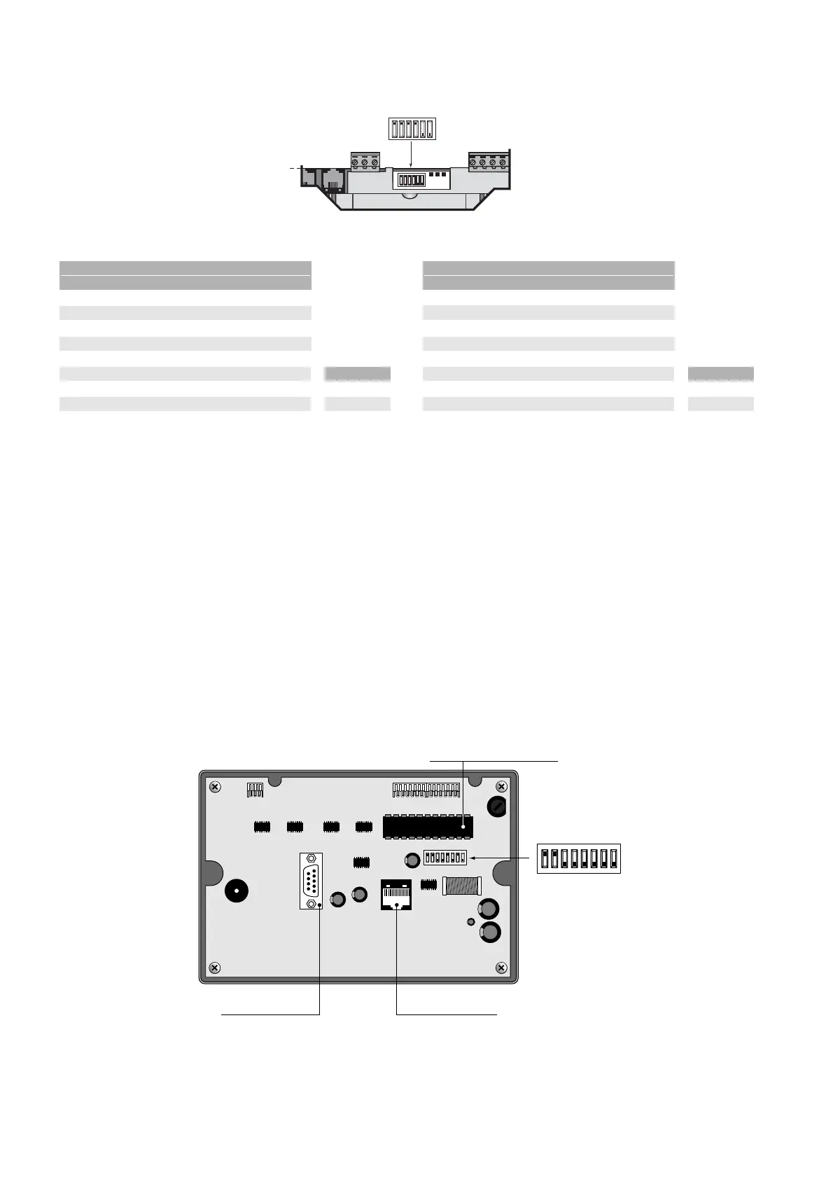
5.2 Indirizzamento terminali
L'indirizzo dei terminali si imposta tramite il banco di dip-switch posti
sul retro.
L'indirizzo è impostabile nel range 1/32 utilizzando i dip-switch 1/6. Il
valore dell'indirizzo si ottiene tramite le tabelle del paragrafo precedente.
Il terminale grafico non necessita dell’indirizzamento in quanto
l’indirizzo viene stabilito dalla EPROM di programma.
La Fig. 5.2.1 rappresenta la scheda terminale vista posteriormente.
AVVERTENZA IMPORTANTE: se il programma applicativo non è
previsto in rete locale pLAN, i dip-switch devono essere posizionati su
0, pena il non funzionamento del programma.
5.1 Addressing the pCO
2
The address can be set in the range 1-31 using the dip-switches 1-5.
The value of the address is obtained as in Tab. 6.1.1.
weights 124816
addr. sw1 sw2 sw3 sw4 sw5 sw6*
0without pLAN network connection
1ONOFFOFFOFFOFF -
2OFFONOFFOFFOFF -
3ONONOFFOFF OFF -
4OFFOFFONOFFOFF -
.... .... .... .... .... .... …. status
.... .... .... .... .... .... …. ON 1
31 ON ON ON ON ON - OFF 0
Tab. 5.1.1
Formula:
address=w(SW1)+w(SW2)+w(SW3)+w(SW4)+w(SW5);
application example – fit for address 19:
19=1+2+16= p(SW1)+p(SW2)+p(SW5).
*NOTE: dip-switch no. 6 on the pCO
2
is not connected and thus its
position has no effect.
5.2 Addressing the terminals
The address of the terminals is set using the dip-switches at the rear.
The address can be set in the range 1/32 using dip-switches 1/6.The
value of the address is calculated using the tables in the previous
paragraph.
The graphic terminal does not need to be addressed as the address is
established by the program EPROM.
Fig. 5.2.1 shows the rear view of the terminal board.
IMPORTANT WARNING: if the application software is not featured in
the local pLAN network, the dip-switches must be set to 0, otherwise
the program will not work.
36
pCO
2
- cod. +030221835 rel. 3.0 - 18.02.03