S&2ð
cod. Carel +030221826 rel. 2.0 dated 03/10/02
9
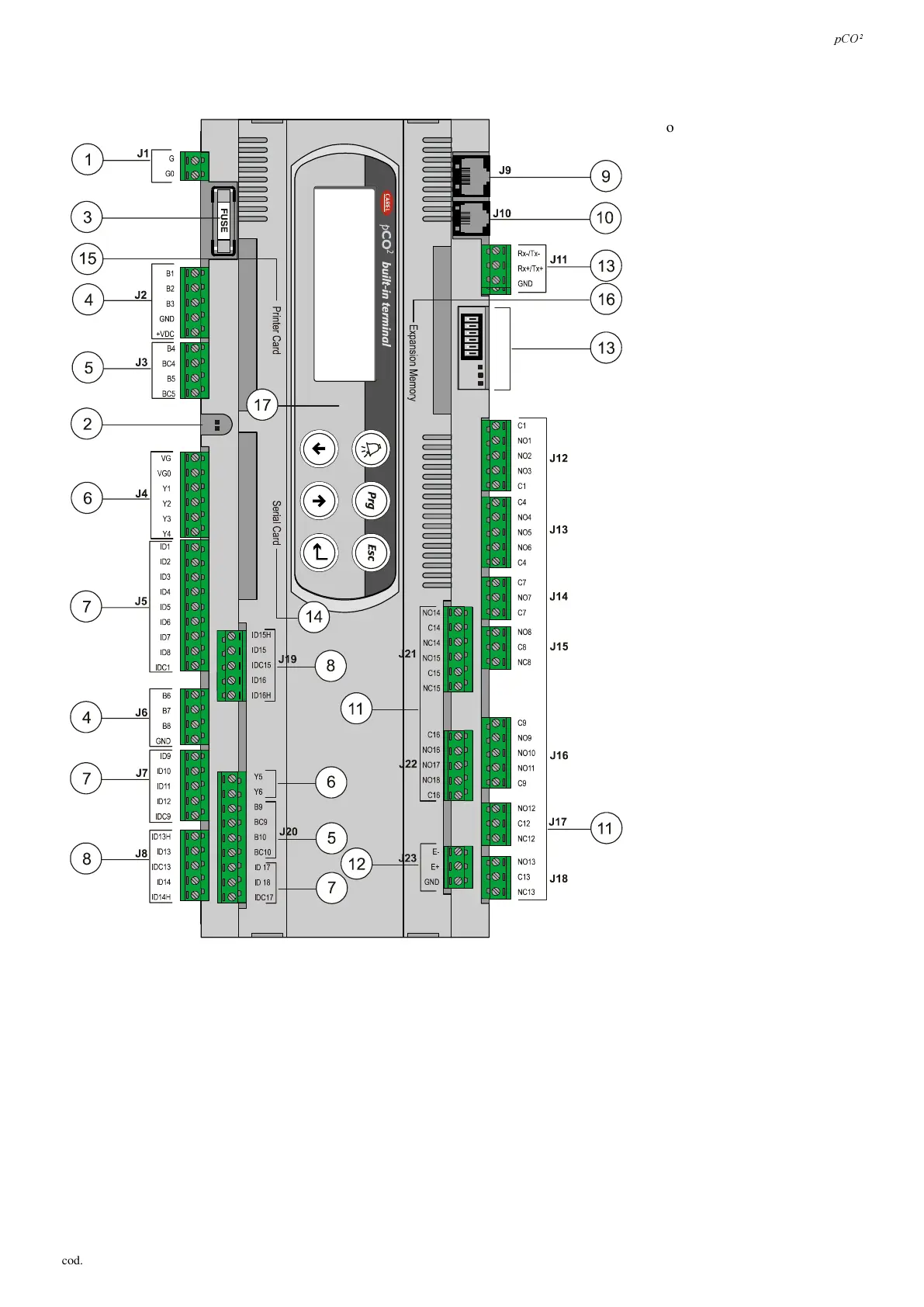
The following is a description of the pCO
2
with reference to the basic layout.
1. Power connector [G(+), G0(-)];
2. Yellow power LED, and red
alarm LED;
3. 250Vac, 2A slow-blow fuse (T2
A)
4. universal analogue inputs, NTC,
0/1V, 0/10V, 0/20mA, 4/20mA;
5. passive analogue inputs, NTC,
PT1000, ON/OFF;
6. analogue outputs, 0/10V;
7. digital inputs, 24Vac/Vdc;
8. digital inputs, 230Vac or
24Vac/Vdc;
9. connector for synoptic terminal;
10. connector for all standard
terminals, PCOT*, PCOI*, in the
pCO
2
series
and for downloading
the application software;
11. relay digital outputs;
12. connector for connection to I/O
expansion modules;
13. connector, address definition and
LED for pLAN local network;
14. hatch for inserting the RS485 (for
serial connection to Carel
supervisor) or RS232 serial board
(for modem interface);
15. hatch for inserting the board for
connection to a parallel printer;
16. hatch for inserting the
programming key/memory
expansion;
17. built-in terminal (LCD, buttons
and LEDs).
)LJ
 Loading...


