S&2ð
cod. Carel +030221826 rel. 2.0 dated 03/10/02
18
7KHIROORZLQJZDUQLQJVPXVWEHUHVSHFWHGIRUFRUUHFWFRQQHFWLRQ
• electrical power supply different from that specified can seriously damage the system;
• use cable plugs suitable for the terminals being used. Loosen each screw and insert the cable plug, then tighten the screws. At
the end of the operation lightly tug the cables to check that they are tight;
• separate as much as possible the probe signal and digital input cables from the inductive load and power cables, to avoid
possible electromagnetic disturbance. 1HYHUXVHWKHVDPHFKDQQHOOLQJLQFOXGLQJWKDWXVHGIRUWKHHOHFWULFDOFDEOHVIRU
WKHSRZHUFDEOHVDQGSUREHFDEOHV. Avoid the probe cables being installed in the immediate vicinity of power devices
(contactors, circuit breakers or others);
• reduce the length of the sensor cables where possible and avoid spiralling around power devices. The probe connection must
be made using shielded cables (minimum cross-section for each lead: 0.5 mm
2
);
• avoid touching or nearly-touching the electronic components on the boards, to avoid (extremely dangerous) electrostatic
discharges from the user to the components;
• if the power supply transformer secondary is earthed, check that the ground wire corresponds to the lead which goes to the
control and enters terminal *;
• separate the power supply to the digital outputs from the power supply to the pCO
2
;
• do not fasten the cables to the terminals by pressing the screwdriver with excessive force, to avoid damaging the pCO
2
.
&RQQHFWLQJWKHDQDORJXHLQSXWV
The pCO² analogue inputs can be configured for the more common sensors on the market: NTC, PT1000, 0÷1V, 0÷10V,
0÷20mA, 4÷20mA. The different types of sensors can be selected via a parameter in the user terminal (if featured in the
application software).
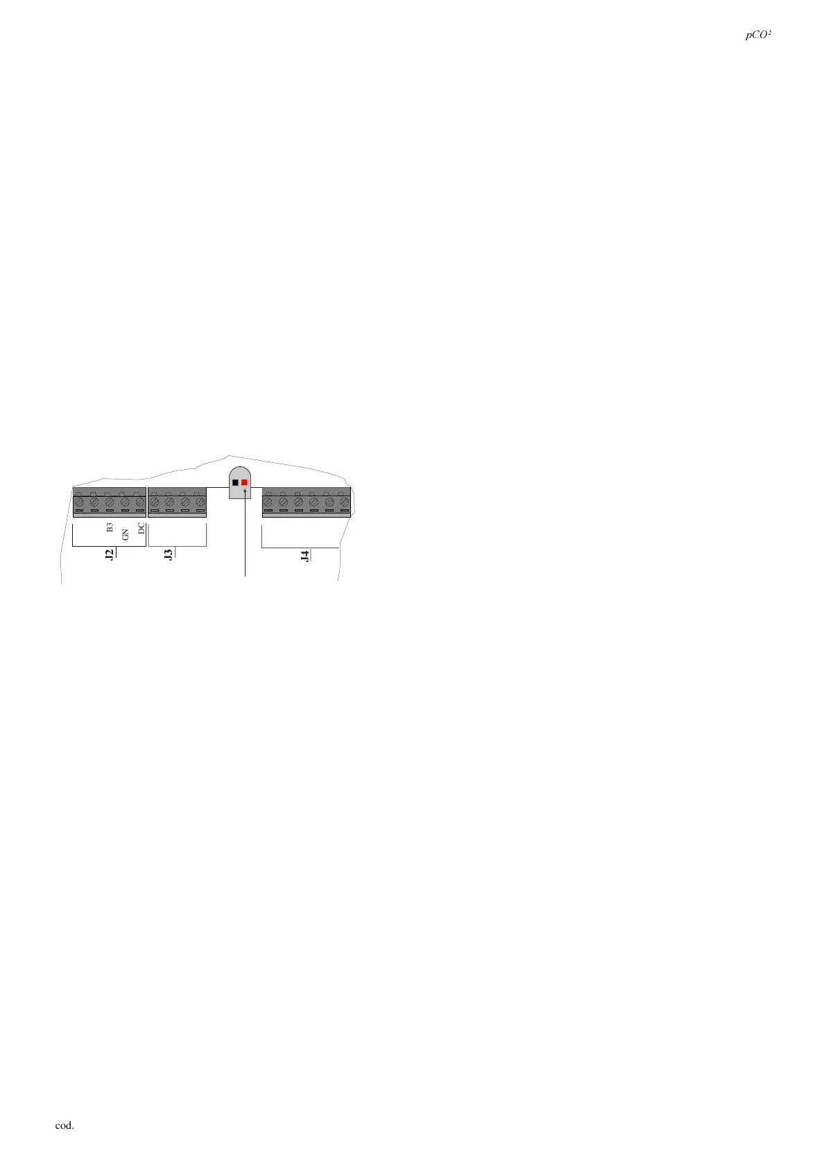
127(: the 21Vdc available at the +VDC terminal can be used for the
power supply to the active probes, the maximum current being 200mA,
protected by circuit-breaker against short-circuits. The activation of the
latter is signalled by the switching on of the red LED on the right (see
Fig. 4.4.1).
B4
BC4
B5
BC5
VG
VG0
Y1
Y2
Y3
-
-
LED
-
B2
B3
GND
+VDC
B1
)LJ
 Loading...


