S&2ð
cod. Carel +030221826 rel. 2.0 dated 03/10/02
46
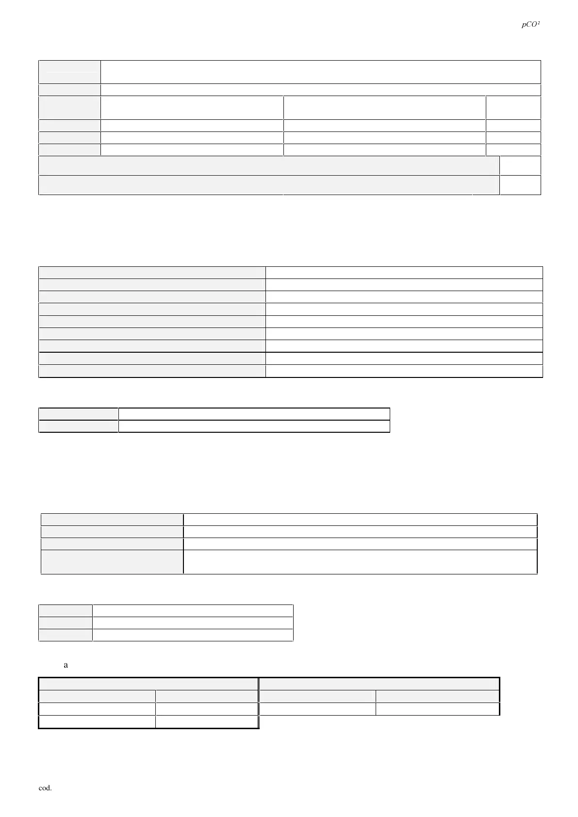
'LJLWD OLQSXW V
W\SH
optically-isolated inputs, 24Vac 50/60Hz or 24Vdc or 230Vac 50/60Hz.
For all the 230 Vac inputs the insulation is the main one.
PD[LPXPQR
8, 14, 18, respectively on the SMALL, MEDIA, LARGE boards, according to the combinations described below:
ERDUGVL]H
no.
.
optically-isolated inputs at
24Vac 50/60Hz or 24Vdc
no.
.
optically-isolated inputs at
24Vac/Vdc or 230Vac 50/60Hz
total inputs
60$//
8 none 8
0(',80
8 + 4 2 14
/$5*(
8 + 4 + 2 2 + 2 18
PLQLPXPLPSXOVHGHWHFWLRQWLPHIRUGLJLWDOLQSXWQRUPDOO\RSHQRSHQFORVHGRSHQLQ$&DQG'&PV
100
PLQLPXPLPSXOVHGHWHFWLRQWLPHIRUGLJLWDOLQSXWQRUPDOO\FORVHGFORVHGRSHQFORVHGLQ$&DQG'&PV
200
7DE
:$51,1*6IRUGLJLWDOLQSXWVDW9DF
• 230Vac 50/60Hz (+10%, -15%);
• each group of two inputs at 24 Vac/Vdc or 230 Vac has the same common pole, and thus works both at 24Vac/Vdc or 230Vac;
$QDORJXHRXWSXWV
PD[LPXPQR
4, 4, 6, respectively on the SMALL, MEDIA, LARGE boards
W\SH
0÷10Vdc optically-isolated
SRZHUVXSSO\
external 24Vac/Vdc power supply
÷9RXWSXWDFFXUDF\P9 ± 200
<·<P9RXWSXWUHVROXWLRQV
20
<·<P9RXWSXWUHVROXWLRQV
80
VHWWOLQJWLPHDQDORJXHRXWSXWV÷V
2
VHWWOLQJWLPHDQDORJXHRXWSXWV÷V
15
PD[LPXPORDGFXUUHQWP$
10 (corresponding to a minimum impedance of 1kΩ)
7DE
'LJLWDORXWSXWV
PD[LPXPQR
8, 13, 18, respectively on the SMALL, MEDIA, LARGE boards
W\SH
electromechanical relay
7DE
These are divided into 3 groups with two common pole terminals to simplify assembly of the common pole. Pay attention to the current
running through the common terminals, in that this must not exceed the rated current of a single terminal.
The relays are divided in groups, depending on the insulating distance.
Inside one group, the relays have single insulation among them and thus they must support the same voltage (generally 24Vac or
110÷230Vac). Among the groups there is double insulation and so the groups may be at different voltage.
JURXSV
1, 2, 3, 4, 5, 6, 7 - 8 (alarm relay) - 9, 10, 11, 12, 13 – 14, 15 - 16, 17, 18
12FRQWDFWV
all with 250Vac varistor protection
FKDQJHRYHUFRQWDFWV
5 with 250Vac varistor protection on both contacts
VZLWFKDEOHSRZHUDQGUHODWLYH
HOHFWULFDOSDUDPHWHUV
2500VA, 250Vac, 8A resistive, 2A FLA, 12A LRA according to UL873
2A resistive, 2A inductive, cos ϕ=0.4, 2(2)A according to EN 60730-1
7DE
&RQQHFWLRQWRWKHXVHUWHUPLQDO
W\SH
asynchronous half duplex with 2 dedicated leads
FRQQHFWRU
6 way telephone cable
GULYHU
balanced differential CMR 7 V (RS485 type)
7DE
The maximum allowable distances between the terminal and the pCO
2
are reported in Tab. 8.2.5.2.
WHOHSKRQHFDEOH $:*VKLHOGHGFDEOH
FDEOHUHVLVWDQFHΩP
PD[LPXPGLVWDQFHP
FDEOHUHVLVWDQFHΩP
PD[LPXPGLVWDQFHP
≤ 0.14
600
≤ 0.078
600
≤ 0.25
400
7DE
 Loading...


