Do you have a question about the Carel pGD0/pGD1 and is the answer not in the manual?
Details the physical layout and connectors of the PCO³ controller with a key.
Lists and describes the signals for each connector on the PCO³ controller.
Explains the features and grouping of PCO³ digital relay outputs.
Covers power supply, CPU, memory, and clock specifications for PCO³ controllers.
Lists and describes signals for each connector on the pCO¹ controller.
Explains the features and grouping of pCO¹ digital relay outputs.
Covers power supply, CPU, memory, and clock specs for pCO¹ controllers.
Lists and describes signals for each connector on the pCO controller.
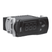
Introduces graphic terminals, detailing PGD0 and PGD1 models and their specifications.
Describes PGD2 and PGD3 graphic displays, mentioning resolutions and color capabilities.
Details how to connect user terminals to the pCO controller using telephone or shielded cables.
Covers environmental conditions, positioning, and wiring procedures for controller installation.
Provides detailed instructions on laying out wires, separating power and control sections, and cable crossing.
Lists warnings regarding installation standards, appliance housing, and repair procedures.
Explains the pLAN network concept, communication speed, and connectable devices.
Details connecting pGD0/1 terminals to pCO via telephone cable and setting addresses.
Details connecting pGD2/3 terminals, setting network address, baud rate, and monitoring status.
Explains connecting and configuring the Aria terminal, including parameter setting via keypad or hardware key.
Details how to set the pLAN address for pCO controllers using a terminal.
Lists and describes various optional serial boards for pCO controllers.
Details optional serial boards like RS485, RS232 modem, Ethernet, and BACnet MSTP.
Describes serial boards for tLAN, MP-Bus, and RS232 connections.
Explains how to use the WinLoad software for updating firmware and managing controller files.
Lists checks for issues related to the unit not starting or the power LED being off.
Guides on interpreting LED signals for error indication during operation.
Offers solutions for LCD display issues, including checking software and connections.
Provides checks for issues related to incorrect readings from input signals.
Provides checks for issues causing the pCO to repeatedly enter Watch-dog mode.
Offers troubleshooting steps for serial connection issues to the local supervisor.
Lists checks for when the user terminal becomes unresponsive.
| Brand | Carel |
|---|---|
| Model | pGD0/pGD1 |
| Category | Controller |
| Language | English |