SOXJLQ
Cod. +030221881 rel. 1.0 - 11/02/2000 6
+$5':$5(6758&785(
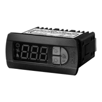
The instruments in the PJ32* series are temperature controls used to manage refrigeration units (showcases and display cases). An
application diagram is shown in the
figure; also indicated are the possible
accessories and expansion modules, as
well as the connections for the inputs and
outputs:
1. instrument;
2. plug-in frame;
3. temperature probes;
4. power transformer (according to the
models);
5. RS485 serial adapter module;
6. HACCP module;
7. parameter programming key.
This manual describes the characteristics
of the instrument, and only briefly
mentions the accessories and expansion
modules.
The connection of the RS485 or HACCP
expansion modules is mutually
exclusive.
0HDQLQJRIWKHLQSXWV
DQGRXWSXWV
GHVFULSWLRQ
(numbering of terminals, with reference to Fig. 2.1)
32:(5
6833/<
terminals 8 and 9; the value of the power supply can be 230Vac, 115Vac or 12Vac/Vdc. The effective value is
indicated on the connection label
WHPSHUDWXUH
SUREHV
terminals 5 and 6 are for the ambient temperature probe (control)
terminals 6 and 7 are for the defrost temperature probe (defrost), when featured
according to the code, connection is for standard Carel NTC or PTC probes
GLJLWDOLQSXW
terminals 6 and 7 are for the digital input from free contact, when featured
UHOD\RXWSXWV
the group of terminals numbered 1, 2, 3, 4 are for the connection of the relay outputs.
The assignment of the outputs can change according to the code , the effective assignment is indicated on the
connection label.
- For instrument codes with one relay only, the changeover contact is available for compressor control, using
terminals 1, 2, 3.
- For instrument codes with two relays, the changeover contact is available for defrost control, on terminals 1,
2, 3, and the closing contact for the compressor relay, on terminals 3 and 4. Terminal 3 is common for the two
relays, thus the current at the terminal will be the sum of the two.
- For instrument codes with three relays, terminal 1 is used for the compressor control, terminal 3 for fan
control, terminal 4 for defrost control and terminal 2 is the common of all three relays. The current at terminal
two will be the sum of the three outputs.
VHULDO
FRQQHFWLRQ
the four-pin connector is for connection to the RS485 serial and HACCP adapters, and for connection of the
parameter copy key. This connection is not present on the
(FR
models
7DE
Power
230Vac
Power
230Vac
Power
230Vac
115Vac
)LJ
 Loading...