+050004210- rel. 1.0 - 16.07.2013
Descrizione
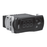
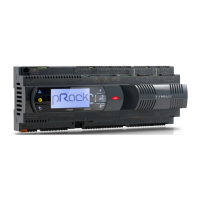
PJS6* rappresenta una gamma di regolatori elettronici a microprocessore con
visualizzazione a LED realizzati per la gestione di unità frigorifere, vetrine e
banchi frigo.
Caratteristiche tecniche
alimentazione (*) 230 Vac +10 /-15% 50/60 Hz; 115 Vac +10 /-15% 50/60 Hz
12 Vac +10/-15% 50/60 Hz classe 2; 12 Vdc +10/-20% classe 2
potenza nominale 3,5 VA
ingressi (*) sonda NTC o PTC 1 o 3 ingressi
ingresso digitale in alternativa a terza sonda
uscite relè (*) relè 2 Hp UL: 12 A Res. 12 FLA 72 LRA - 240 Vac (***),
UL: 12 A Res. 10 FLA 60 LRA - 240 Vac (****)
EN60730-1: 10(10) A 250 Vac (**)
relè 16 A UL: 12 A Res. 5 FLA 30 LRA - 240 Vac C300,
EN60730-1: 12(2) A NO/NC, 10(4) A fi no 60 °C NO,
2(2) A CO - 250 Vac
relè 8 A UL: 8 A Res. 2 FLA 12 LRA - 240 Vac C300,
EN60730-1: 8(4) A NO, 6(4) A NC, 2(2) A CO - 250 Vac
tipo di sonda (*) NTC Std CAREL 10 KΩa 25 °C, PTC Std CAREL 985 Ω a 25 °C
connessioni (*) - morsetti fi ssi a vite per cavi con sez. da 0,5 mm
2
a 1,5 mm
2
- morsetti estraibili per blocchetti a vite o con contatto a
crimpare (sez. cavo fi no a 2,5 mm
2
).
- corrente nominale massima per morsetto 12 A.
montaggio (*) per terminale: mediante viti dal frontale o con staff e posteriori
visualizzazione display LED 3 cifre con segno (-199…999) e punto decimale;
sei LED di stato
condizioni di funzionamento -10T50 °C - umidità <90% U.R. non condensante
condizioni di immagazzinamento -20T70 °C - umidità <90% U.R. non condensante
intervallo di rilevazione -50T90 °C (-58T194 °F) - risoluzione 0,1 °C/°F
grado di protezione frontale montaggio a quadro con guarnizione: IP65 tipo 1
contenitore terminale plastico, 81x36x65 mm
classifi c. secondo la protezione
contro le scosse elettriche
classe II per incorporamento adeguato
inquinamento ambientale normale
PTI dei materiali di isolamento 250 V
periodo delle sollecitazioni
elettriche delle parti isolanti
lungo
categ. di resistenza al calore e al fuoco categoria D (UL94 - V0)
immunità contro le sovratensioni categoria 1
tipo di azione e disconnessione contatti relè 1C
n.ro di cicli di manovra delle
operazioni automatiche relè (*)
EN60730-1: 100.000 operazioni
UL: 30.000 operazioni (250 Vac)
classe e struttura del software classe A
pulizia dello strumento utilizzare esclusivamente detergenti neutri ed acqua
lunghezza max. cavi seriale: 1 km, sonde: 30 m, relè: 10 m
Tab. 2
Avvertenza: non passare cavi di potenza a meno di 3 cm dalla parte inferiore del dispositivo o dalle sonde; per le
connessioni usare solo cavi di rame.
(*) Le caratteristiche indicate si di erenziano a seconda del modello. (***) solo per i modelli PJS6 (M, S, X)*
(**) T OFF minimo tra due start motore deve essere maggiore di 60 s. (****) solo per i modelli PJS6(C, Y)*
LED e funzioni associate
Icona Funzione Normale funzionamento Start up
ON OFF blink
compressore acceso spento richiesto ON
ventola acceso spento richiesto ON
defrost acceso spento richiesto ON
AUX aux / heater uscita accesa uscita spenta - ON
allarme tutti nessun allarme - ON
orologio RTC presente e
abilitato, ed è stata
impostata almeno
una fascia oraria
RTC assente o disabilit.;
oppure non è stata
impostata nemmeno
una fascia oraria
- ON se RTC
presente
Tab. 4
Tabella attivazione funzioni tramite i tasti
Tasto Normale funzionamento Start up
pressione del singolo tasto
più di 3 s: alterna stati ON/OFF -
più di 3 s: attiva/disattiva defrost Premuti
insieme
attivano
procedura
RESET
parametri
per 1 s
visualizza cod.
vers. fi rmware
- 1 s.: visualizza/permette di impostare set point per 1 s RESET
banco EZY
corrente
- più di 3 s: accesso menù impostazione parametri
(inserire password ‘22’)
- Tacita allarme acustico (buzzer)
Tab. 5
Impostazioni del set point (valore di temperatura desiderato)
• premere per 1 s SET, dopo alcuni istanti il valore impostato per St1 lampeggia;
• aumentare o diminuire tale valore con UP o DOWN;
• premere SET per confermare il nuovo valore.
Se abilitato il set point2 (H6=1),
• tenendo premuto SET, dopo alcuni istanti il valore impostato per St2 lampeggia;
• aumentare o diminuire tale valore con UP o DOWN;
• premere SET per confermare il nuovo valore.
ON/OFF dello strumento
Premere per più di 3 s UP. In questa condizione gli algoritmi di regolazione e
defrost sono disabilitati e lo strumento alterna la visualizzazione a display del
messaggio “OFF” a quella della temperatura della sonda impostata.
Sbrinamento manuale
Premere per più di 3 s DOWN (si attiva solo se sussistono le condizioni di
temperatura).
Accesso e modi ca parametri tipo F (frequenti) e tipo C
(con gurazione)
1. premere SET per 3 s (sul display comparirà “PS”);
2. - per accedere al menù parametri di tipo F e C digitare la password “22” con
UP/DOWN;
- per accedere solo al menù parametri F premere SET (senza digitare la password);
3. navigare all’interno del menù parametri con UP/DOWN;
4. per visualizzare/modifi care i valori del parametro visualizzato premere SET,
quindi UP/DOWN ed infi ne SET per confermare la modifi ca (si ritorna così al
menù dei parametri).
Per salvare defi nitivamente tutti i valori modifi cati ed uscire dal menù parametri
premere SET per 3 s;
Per uscire dal menù senza salvare i valori modifi cati (uscita per time out) non
premere alcun tasto per almeno 60 s.
Dimensioni (mm) / Dimensions (mm)
71x29
10
3
33
74
81
36
58
65,29
28.5
Montaggio a pannello / Panel mounting
Frontale (con 2 viti ø 2,5x12 mm) / Front (with 2 screws ø 2,5x12 mm)
max 2,5
1
2 3
Da dietro (con 2 staff e posteriori) / Rear (with 2 quick-fi t side brackets)
1
2
PUSH
Collegamenti elettrici / Electrical connections
1 2 3 4 5
6 7
9 10 11
8
L
L N
230V~
-10T50
Use copper conductors only
Ref. C614A233/R0
8(4)A 10(10)A EN60730-1
8A 2FLA 12LRA 12A 12FLA 72LRA UL 873
P2
P1
NTC
PROBES
or
SERIAL
CONV
PROG.
KEY
DI / NTC
AUX
250 Vac
OUT1
OUT2
1 2 3 4 5 6 7
9
10 118
L
L N
Use copper conductors only
Ref. C614A234/R1
8(4)A 10(10)A EN60730-1
8A 2FLA 12LRA 12A 10FLA 60LRA UL 873
P2
DI / NTC
P1
NTC
PROBES
or
SERIAL
CONV
PROG.
KEY
-10T50
250 Vac
230V~
OUT1
OUT2
OUT3
AUX
(*) Confi gurabile con VPM anche come FAN o SBRINAMENTO / Can also be confi gured as
FAN or DEFROST using VPM
controlli elettronici per la gestione di intervalli di temperatura /
electronic controller for range temperature management
PJS6
Tabella allarmi / Alarms table
Codice allarme Buzzer e relè allarme LED Descrizione allarme Parametri coinvolti
E0 attivi ON errore sonda 1 -
E1 non attivi ON errore sonda 2 [d0 = 0 / 1]
E2 non attivi ON errore sonda 3 [A4=10]
IA attivi ON allarme esterno [A4 = 1] [+A7]
dOr attivi ON allarme porta aperta [A4 = 7/8][+A7]
LO attivi ON allarme bassa temperatura [AL] [Ad]
HI attivi ON allarme alta temperatura [AH] [Ad]
EE non attivi ON errore parametri macchina -
EF non attivi ON errore parametri funzionamento -
Ed non attivi ON defrost nito per timeout [dP] [dt] [d4] [A8]
dF non attivi OFF defrost in esecuzione [d6=0]
EtC non attivi ON allarme orologio se fasce attive
Alarm code buzzer and alarm relay LED Description Parameters involved
E0 active ON probe 1 error -
E1 inactive ON probe 2 error [d0 = 0 / 1]
E2 inactive ON probe 3 error [A4=10]
IA active ON external alarm [A4 = 1] [+A7]
dOr active ON
open door alarm
[A4 = 7/8][+A7]
LO active ON
low temperature alarm
[AL] [Ad]
HI active ON
high temperature alarm
[AH] [Ad]
EE inactive ON
unit parameter error
-
EF inactive ON
operating parameter error
-
Ed inactive ON defrost ended by timeout [dP] [dt] [d4] [A8]
dF inactive OFF defrost running [d6=0]
EtC inactive ON clock alarm if bands active
Tab. 1
Description
PJS6* is a range of electronic microprocessor controllers with LED display,
designed to manage refrigeration units, showcases and cabinets.
Technical speci cations
power supply (*) 230 Vac +10 /-15% 50/60 Hz; 115 Vac +10 /-15% 50/60 Hz
12 Vac +10/-15% 50/60 Hz class 2; 12 Vdc +10/-20% class 2
rated power 3,5 VA
inputs (*) NTC or PTC probes 1 or 3 inputs.
Digital input as alternative to third probe
relay outputs (*) relay 2 Hp UL: 12 A Res. 12 FLA 72 LRA - 240 Vac (***),
UL: 12 A Res. 10 FLA 60 LRA - 240 Vac (****)
EN60730-1: 10(10) A 250 Vac (**)
relay 16 A UL: 12 A Res. 5 FLA 30 LRA - 240 Vac C300,
EN60730-1: 12(2) A NO/NC, 10(4) A up to 60 °C NO,
2(2) A CO - 250 Vac
relay 8 A UL: 8 A Res. 2 FLA 12 LRA - 240 Vac C300,
EN60730-1: 8(4) A NO, 6(4) A NC, 2(2) A CO - 250 Vac
type of probe (*) NTC Std CAREL 10 KΩa 25 °C, PTC Std CAREL 985 Ω a 25 °C
connections (*) - screw terminals for cables with cross-sect. from 0.5 mm
2
to 1.5 mm
2
.
- Plug-in terminals for screw blocks or with crimped contact (cable
cross-sect. up to 2.5 mm
2
).
- Rated maximum current per terminal 12 A.
assembly (*) terminal: using screws from the front panel or with rear brackets.
display 3 digit LED display with sign (-199 to 999) and decimal point;
six status LEDs
operating conditions -10T50 °C - humidity <90% rH non-condensing
storage conditions -20T70 °C - humidity <90% rH non-condensing
range of measurement -50T90 °C (-58T194 °F) - resolution 0.1 °C/°F
front panel index of protection panel installation with IP65 type 1 gasket
case plastic terminal, 81x36x65 mm
front panel index of protection class II when suitably integrated
environmental pollution normal
PTI of the insulating material 250 V
period of stress across the insulating
parts
long
category of resist. to heat and fi re category D (UL94 - V0)
immunity against voltage surges category 1
type of action and disconnection 1C relay contacts
no. of relay automatic operating
cycles (*)
EN60730-1: 100.000 operations
UL: 30.000 operations (250 Vac)
software class and structure class A
cleaning the instrument Only use neutral detergents and water.
cable max. lenght serial: 1 km, probes: 30 m, relay: 10 m
Tab. 2
Warning: do not run the power cable less than 3 cm from the bottom part of the device or from the probes; for
the connections only use copper wires.
(*) The features indicated di er according to the model. (***) only for PJS6 (S, X)* models
(**) T OFF min. time between two starts of the motor must be greater than 60 s. (****) only for PJS6 (C, Y)*
LEDs and associated functions
Icon Function Normal operation Start up
ON OFF blink
compressor ON OFF request ON
fan ON OFF request ON
defrost ON OFF request ON
AUX aux / heater output on output off -ON
alarm all no alarm - ON
clock RTC fi tted and
enabled, at least a
time band set
RTC not fi tted or
disabled, not even a
time band set
- ON if RTC
fi tted
Tab. 4
Table of functions activated by the buttons
Button Normal operation Start up
pressing the button alone
more than 3 s: toggle ON/OFF
-
more than 3 s: start/stop defrost
Pressed
together start
parameter
RESET
procedure
for 1 s display
fi rmware vers.
code
- 1 s.: display/set the set point for 1 s RESET
current EZY set
- more than 3 s: access parameter setting menu
(enter password ‘22’)
- mute audible alarm (buzzer)
Tab. 5
Setting the set point (desired temperature value)
• press SET for 1 s, after a few moments the value set for St1 fl ashes;
• increase or decrease the value using UP or DOWN;
• press SET to confi rm the new value.
If set point 2 is enabled (H6=1),
• press and hold SET, after a few moments the value set for St2 fl ashes;
• increase or decrease this value using UP or DOWN;
• press SET to confi rm the new value.
Switching the device ON/OFF
Press UP for more than 3 s. The control and defrost algorithms are now disabled
and the instrument displays the message “OFF” alternating with the temperature
read by the set probe.
Manual defrost
Press for DOWN more than 3 s (the defrost starts only the temperature conditions
are valid)
Access and setting type F (frequent) and type C (con guration)
parameters
1. press SET for 3 s (the display will show “PS”);
2. - to access the type F and C parameter menu, enter the password “22” using
UP/DOWN;
- to access the F parameter menu only, press SET (without entering the
password);
3. scroll inside the parameter menu using UP/DOWN;
4. - to display/set the values of the parameter displayed, press SET, then UP/
DOWN and fi nally SET to confi rm the changes (returning to the parameter
menu).
To save all the new values and exit the parameter menu, press SET for 3 s;
To exit the menu without saving the changed values (exit by timeout) do not
press any button for at least 60 s.
Fig. 1
Fig. 2
Fig. 3
Fig. 4
Fig. 5
IMPORTANT WARNINGS: The CAREL product is a state-of-the-art product, whose operation is
speci ed in the technical documentation supplied with the product or can be downloaded, even prior
to purchase, from the website www.carel.com. - The client (builder, developer or installer of the nal
equipment) assumes every responsibility and risk relating to the phase of con guration the product
in order to reach the expected results in relation to the speci c nal installation and/or equipment.
The lack of such phase of study, which is requested/indicated in the user manual, can cause the nal
product to malfunction of which CAREL can not be held responsible. The nal client must use the
product only in the manner described in the documentation related to the product itself. The liability
of CAREL in relation to its own product is regulated by CAREL’s general contract conditions edited on the
website www.carel.com and/or by speci c agreements with clients.
NO POWER
& SIGNAL
CABLES
TOGETHER
READ CAREFULLY IN THE TEXT!
WARNING: separate as much as possible the probe and digital input signal cables from the cables
carrying inductive loads and power cables to avoid possible electromagnetic disturbance. Never run
power cables (including the electrical panel wiring) and signal cables in the same conduits.
DISPOSAL OF THE PRODUCT: The appliance (or the product) must be disposed of separately in
accordance with the local waste disposal legislation in force.
NORMATIVE DI SICUREZZA - conforme alle Normative europee in materia.
Precauzioni d’installazione:
• i cavi di collegamento devono garantire l’isolamento no a 90 °C;
• per le versioni 12 Vac utilizzare trasformatori Classe II. Per il rispetto delle normative EN 61000-4-4, EN 61000-4-5, EN 61000-4-11,
EN 61000-4-6, EN 60730-1, il trasformatore deve essere uno dei modelli indicati (vedi Listino Prezzi CAREL). Per le versioni 12 Vac/
dc, non essendo possibile garantire il doppio isolamento tra i connettori di alimentazione e le uscite relè, si raccomanda di utilizzare
carichi alimentati solamente in bassissima tensione di sicurezza ( no a 42 V nominali di valore e cace);
• prevedere almeno 10 mm di distanza tra il contenitore e parti conduttive vicine;
• collegamenti degli ingressi digitali e analogici inferiori a 30 m di distanza; adottare le adeguate misure di separazione dei cavi
per il rispetto delle normative suddette.
• Bloccare bene i cavi di connessione delle uscite per evitare contatti con parti in bassissima tensione di sicurezza
.
SAFETY STANDARDS - compliant with the relevant European standards.
Installation precautions:
• the connection cables must guarantee insulation up to 90 °C;
• for 12 Vac versions use Class II transformers. To ensure compliance with the immunity standards (surge), the transformer must
be one of the models speci ed (see the CAREL price list). For the 12 Vac/dc versions, as double insulation cannot be guaranteed
between the power supply and the relay outputs, only use safety low voltage loads (up to 42 V e ective rated value);
• ensure a space of at least 10 mm between the case and the nearby conductive parts;
• digital and analogue input connections less than 30 m away; adopt suitable measures for separating the cables so as to ensure
compliance with the immunity standards;
• Secure the connection cables of the outputs so as to avoid contact with very low voltage parts.
(*)
VPM: visual parameter manager in http://ksa.carel.com - VPM: visual parameter manager
at http://ksa.carel.com