plug-in
Cod. +030221881 rel. 1.5 - 26/10/10
39
8. AVAILABLE ACCESSORIES
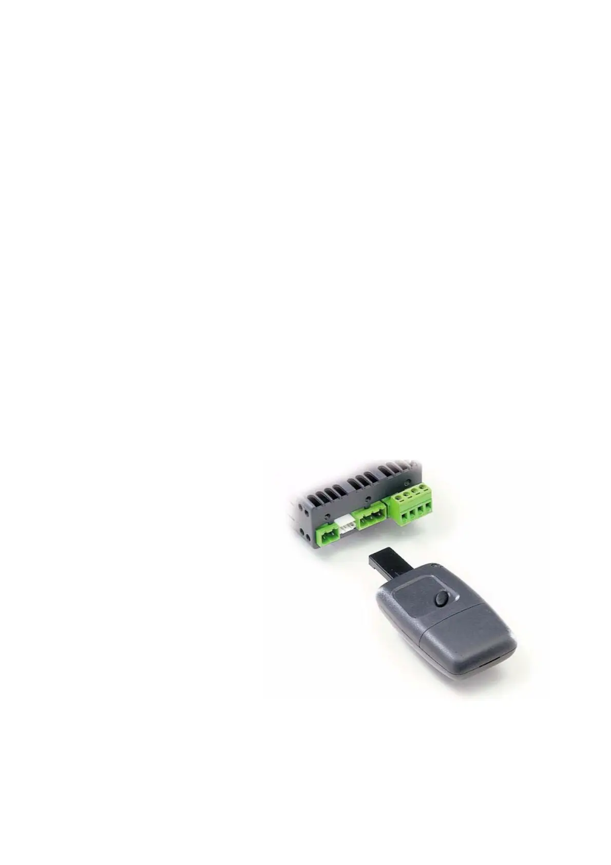
8.1 Key for copying the parameters
Duplicates the configuration of an instrument (set values of all the parameters and visibility flags), allowing them to be transferred
to other instruments, as long as these have the same hardware configuration (same code).
The key consists of a remote control type box with a connecting cable to the serial port of the instrument, and features an on/off
button and a two-colour signal LED (red/green).
It is powered by a 12Vdc alkaline battery, such as the Philips VR32 or Duracell MN21, or equivalent.
The key must be connected to the instrument when it is off (it doesn’t need to be powered), as the power to the instrument is
supplied by the key itself.
Pressing and holding the activation button transfers the data. The two-colour LED signals the operating status, indicating the
execution and completion of the data transfer and any errors. The maximum duration of the operation is around 12 seconds; during
this period the instrument remains off, after which it starts in normal mode.
During the first 12 seconds the consumption of current is reduced, in that the instrument’s LEDs and display are not turned on due
to their high consumption. The button should not be pressed longer than the time required to complete the operation, so as not to
discharge the battery too quickly.
The possible operations are the following:
1. read the parameters from the connected instrument and save them to the key. This operation is always possible and is activated
by setting the two dip-switches 1,2 to position OFF and pressing the activation button for the necessary time;
2. write the parameters from the key to the connected instrument. This is performed by setting dip-switch 2 to position ON and
dip-switch 1 to OFF, and pressing the activation button. This operation can only be performed if the parameters contained in the
key (model) are compatible with the connected instrument;
3. reset the modify parameters flags (minus sign – for H5). This is performed by setting dip-switch 1 to position ON and dip-
switch 2 to OFF, and pressing the activation button. This operation is always possible, and the values of the parameters, apart
from the flag H5, are not modified.
The indications of the two-colour LED are the following:
on for a brief the red LED turns on at low intensity;
data transfer the red LED turns on at high intensity; the activation button must not be released during this period;
operation completed the green LED turns on, the operation is concluded.
in the event of errors, the red and green LEDs will flash to indicate various causes:
1. instrument disconnected or no response;
2. low power (battery);
3. instrument model not compatible;
4. transfer error;
5. instrument EEPROM error.
For a more compete description of the causes of
these errors, please refer to the key instruction
sheet.
Fig. 8.1.1
 Loading...