Do you have a question about the Carl Goldberg Products Ultimate 10-300 and is the answer not in the manual?
| Brand | Carl Goldberg Products |
|---|---|
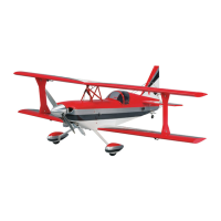
| Model | Ultimate 10-300 |
| Category | Toy |
| Language | English |
List of tools and materials required for aircraft assembly.
Instructions for attaching the top wing using cabane struts.
Installing control horns for surfaces using bolts and nuts.
Method for ensuring proper alignment of control surface hinges.
Attaching aluminum angles to the landing gear plate and motor box.
Drilling holes and filing edges for flush fitting of the landing gear.
Installing axles and aligning the gear legs for proper fit.
Identifying left and right wheel pants and their wood mount blocks.
Drilling holes and securing wheel pants to the landing gear.
Cutting slots in the cowl and aligning it with the fuselage.
Drilling holes and mounting the cowl using screws and washers.
Calculating motor box side length based on engine and cowl measurements.
Marking motor box sides for thrust angles and firewall placement.
Epoxying the firewall and notching it for engine head and muffler.
Aligning the engine with the cowl and securing it to the firewall.
Assembling the fuel tank with three lines and routing them.
Mounting the fuel tank using the laser-cut tank mount.
Mounting the throttle servo and connecting the pushrod.
Placing the fuel tank between holes and securing it with tie wraps.
Installing servos and connecting pushrods to control horns.
Attaching pushrods to the rudder output and horn.
Connecting aileron pushrods to servo arms and control horns.
Locating switches and mounting receiver and batteries.
Connecting servo lead extensions and Y-connectors for radio setup.
Trimming the canopy to fit the hatch and mounting it securely.
Setting the Center of Gravity (CG) 7 inches behind the top wing's leading edge.
Setting elevator, rudder, and aileron throws for optimal flight control.
Checking cabane struts and other hardware for secure attachment with thread lock.
Checking all bolts, linkages, and recommendations for engines, batteries, and servos.