Do you have a question about the Carlin 60200 and is the answer not in the manual?
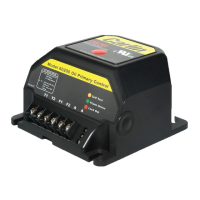
Details proper mounting of the control unit on a 4"x4" junction box, respecting ambient temperature limits.
Emphasizes that all wiring must comply with local and national electrical codes and ordinances.
Outlines essential field checks, including safety timing (TFI) and flame failure tests for verification.
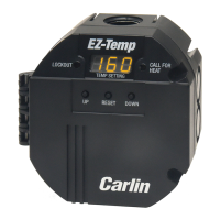
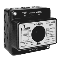
Explains the function and status indications of the unit's diagnostic LEDs for monitoring operation.
Warns against starting the burner with oil/vapor and notes UL requirements for CAD cell self-test.
Details the boot-up test sequence, amber LED behavior upon power application, and self-test failures.
Describes the control's standby state after self-test and its response to a thermostat's call for heat.
Explains the sequence of ignitor, motor activation, and oil valve opening after the self-test.
Provides the procedure for initiating pump prime and notes for optional pump prime sequences.
Explains the TFI time limit for sensing flame and the consequences of insufficient flame leading to lockout.
Details normal run state, conditions leading to control lockout, and the latch-up sequence.
Provides a special, technician-only procedure for resetting the control after three consecutive lockouts.
Describes actions upon flame failure, including recycle, and the motor delay off (post-purge) sequence.
Guides on diagnosing issues when the burner or control does not power on or is in lockout.
Covers diagnosing CAD cell issues like sensing light, resistance checks, and holder problems.
Addresses other potential no-start problems like valve lead voltage, line voltage, and internal faults.
Lists checks for repeated flame failures, including air leaks, nozzle issues, and draft problems.
Details checks for control lockout after the Trial For Ignition period, such as no oil or shorted electrodes.
| Voltage | 120 VAC |
|---|---|
| Frequency | 60 Hz |
| Flame Failure Response Time | 0.8 seconds |
| Safety Standards | UL |
| Operating Temperature Range | -40°F to 150°F (-40°C to 66°C) |