3
Carlin Combustion Technology
MN70200B 101323
Installing and Wiring
The 70200 control must be installed and serviced only by a qualified service technician.
Do not connect an external voltage to the thermostat terminals T1 and T2. This will damage the control
and may result in a dangerous operating condition
Always disconnect power source before wiring to avoid electrical shock or damage to the control. All wiring must
comply with applicable codes and ordinances.
Mounting
The control may be mounted on a 4" x 4" junction box in any convenient location on the burner, furnace or wall. The
location must not exceed the ambient temperature limit, 140°F.
Wiring
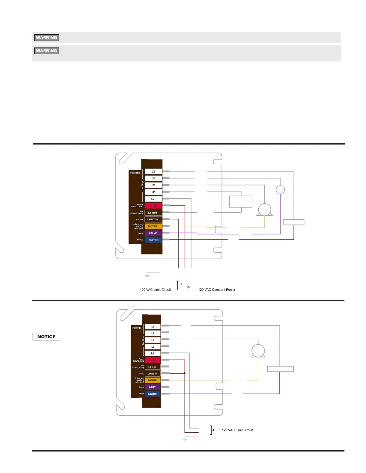
Wiring must comply with local and national electrical codes, and with the following wiring diagrams.
6-Wire
Recommended
Wiring
3-Wire
Replacement
Wiring
When con-
necting to BLACK power
harness wire, without
constant L1 power, wire
nut together L1 (RED)
and Limit In (BLACK)
from control.
M
OV
OIL
VALVE
IGNITION
NOZZLE
LINE HTR
(OPTIONAL)
WHT
WHT
WHT
WHT
BLUE
ORANGE
VIOLET
BURNER
MOTOR
GN
WHT
RED/WHT
BLACK
RED/WHT
WHT
WHT
M
IGNITION
ORANGE
BLUE
BURNER
MOTOR
WHT
RED
WHT
BLK
GN