EN
77-3090-R2 (9/2019)4 / 12www.carlisleft.com
GUN BOX PNEUMATIC CONNECTIONS
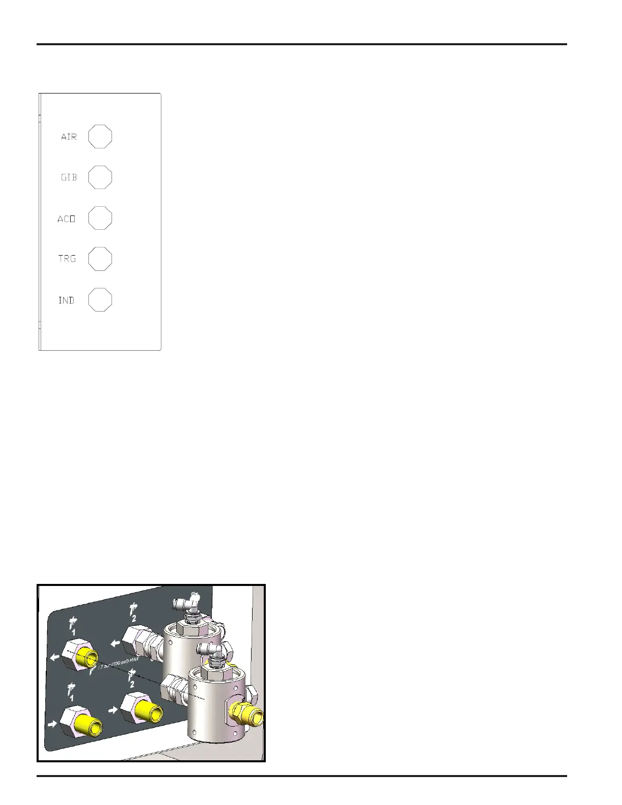
AIR CONNECTION DESCRIPTIONS
AIR — Supply air needed to operate the Gun Box. 75-100 psi [5-7 bar] required.
GIB — Air signal sent to the controller (GIB1, GIB2) when the spray gun is in
the Gun Box and the lid is closed.
ACO — Triggers the Air Cut Off (ACO) Valve at the Air Flow Switch. Enables /
disables the spray gun’s atomizing air.
TRG — Air signal used to trigger the spray gun in the closed box. Receives signal
from system controller (TRG1, TRG2).
IND – Pneumatic indicator shows when gun is triggered. This input is shared
with TRG via a tee. Only the TRG input must connect to the control.
CONNECTING AIR LINES
After mounting the box, use the supplied pneumatic tubing to connect the ush box to the supply air and
GEMS control. Use a length of black 5/32” tubing to provide supply air to the bulkhead ‘AIR’. Adapt to
tubing size as needed.
Use a length of clear tubing to connect the enclosure bulkhead for GIB1 (or GIB2) to the GIB connection of
the ush box.
The second length of clear tubing should run from the ACO connection of the ush box to the elbow
mounted on the air cutoff valve. The ACO labeled solenoid (in the control enclosure) valve should be
plugged at the valve outlet.
A second length of black tubing should connect the ush box TRG connection to the corresponding TRG1
or TRG2 bulkhead on the back of the enclosure.
Ensure all tubing is free from sharp bends and kinks. Keep tubing clear of sharp edges and hot surfaces.
See the diagram on pp. 6-7 for more information.
CONNECTING AIR CUT OFF VALVE
Mount the Air Cut Off valve(s) to the outlet of the airow
switches as shown at left. For more detail, see 77-3087
Air Cut-off Installation Instructions.
Connect the ACO trigger signal tubing as described above.


 To Next Page
 Loading...
