1
15 Gauge finish Nailer
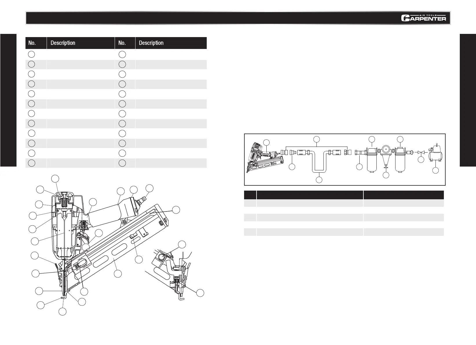
6
Regulator
2
Quick connector
7
Filter
3
Quick coupler
8
Cut -off valve
4
Air hose
9
Air compressor
5
Lubricator
98
COMPATIBLE COMPRESSORS
GUIDELINES FOR PROPER USE AND OPERATION
Be sure to use a proper air compressor with CARPENTER Air Tools. The compressor should be able
to supply a minimal air delivery of 4.7 CFM @ 90 PSI to ensure the compressor can run continuously
with the CARPENTER 15 Gauge finish Nailer.
GENERAL USE
No. Description No. Description
The C1565 is ideal finish nailer for interior trim,exterior trim,baseboards,crown molding,window and
door casings,chair rails and so on, it accepts 15-gauge nails from 1-1/4" up to 2-1/2" in length.The
tool is lightweight and durable, stands up to the elements and provides consistently accurate results
over the life of the tool. An ideal tool for a variety of construction projects, including installation of
asphalt roofing shingles and insulation boards. It also features a high-capacity side-load magazine,
tool-less depth adjustment, durable construction, and more.
•It is recommended that a filter-regulator-lubricator be used and be located as close to the tool
•If a filter-regulator-lubricator is not installed, place up to 6 drops of compressor oil into the air
inlet plug before each use.
•If a filter-regulator-lubricator is installed, keep the air filter clean. A dirty filter will reduce the
air pressure to the tool, which will cause a reduction in power, efficiency, and general
•Verify that all of the connections in the air supply system are sealed in order to prevent air leakage.
Read and follow all the safety instructions at the beginning of this manual and inspect the
air-powered nailer prior to each use in order to ensure that the proper power source is being used
and verify that the tool is in proper working order
Model No. C1565 contact us 1-888-666-1887
KEY PARTS DIAGRAM
TECHNICAL INFORMATION
1
1
2
2
3
3
4
4
5
5
6
6
7
7
8
8
9
9
10
10
11
11
12
12
13
13
22
22
15
15
16
16
14
14
17
17
18
18
19
19
20
20
23
23
24
24
21
21
Top Cover
Air Outlet
Exhaut Cover
Piston O-ring
Piston
Driver Blade
Lock Lever
Nail Feeder(A)
Guide Plate(A)
Push Lever
Outlet(Firing Head)
Blade Guide
Nail Feeder(B)
Valve part
Switching Device
Trigger
Body
Cap
Air Plug
Nail Rail
Nail Stopper
Magazine
Ribbon Spring
Adjuster
1
2
5 7
3
4
3
6
8
9