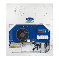
Do you have a question about the Carrier TRANSICOLD 69NT40-489 and is the answer not in the manual?
Details about the compressor, its components, and related parts.
Description of the condenser fan motor, coil, and airflow.
Components of the evaporator section, including fans, coil, heaters, and defrost.
Components within the control box, including switches, breakers, and modules.
Specifications like number of cylinders and model number.
Specifies the type of compressor oil to be used.
Details the quantity of oil for the compressor.
Guidance on checking the oil level via the sight glass.
Procedure for verifying expansion valve superheat.
Specifications for the heater termination thermostat's open/close points.
Cut-in and cut-out pressure settings for the high pressure switch.
Trip settings for circuit breakers CB-1 and CB-2.
Full Load Amps (FLA) for the compressor motor.
Bearing lubrication, FLA, horsepower, rotation, speed, and voltage/frequency.
Bearing lubrication, FLA, horsepower, rotation, speed, and voltage/frequency.
Fuse ratings for control circuit, controller, and DataCorder.
Function and location of the power autotransformer for voltage conversion.
How to adjust the fresh air makeup vent for airflow control.
Functionality of the remote monitoring system and its indicators.
How the suction solenoid valve operates based on set point.
Function to restrict SSV opening under certain conditions.
Use and operation of the water-cooled condenser.
Overview of the controller's functions and capabilities.
Use of memory cards for software loading and configuration.
Software that defines unit components and sensor configurations.
Description of the keypad, display module, and controller module.
Explanation of control ranges and modes for temperature management.
Operation for perishable range, including conventional mode.
Activation and operation of the dehumidification mode.
User-selectable mode for power saving purposes.
Extension of dehumidification mode for precise control.
Control method for frozen range using compressor cycling.
Deactivation of economy mode and its operation in frozen settings.
Restrictions and behavior of bulb mode with frozen set points.
Accessing and explanation of 37 operator-selectable functions.
Function of the suction modulation valve.
Operation of the suction solenoid valve for refrigerant flow.
Function of current sensors for control and diagnostics.
How mains voltage is determined and used for settings.
Function of the ambient sensor measuring outside temperature.
Display-only temperature of the compressor suction.
Measured temperature near the compressor discharge valve.
Display of compressor suction pressure via transducer.
Display of discharge or condenser pressure.
Records total compressor run time.
Displays relative humidity for units with a humidity sensor.
Tests the optional battery pack's voltage and status.
Sensor location and function for defrost initiation/termination.
Defines unit actions during sensor failures or out-of-range conditions.
Determines temperature bandwidth for in-range light illumination.
Settings for relative humidity control and dehumidification.
User-selectable mode for power saving purposes.
Extension of dehumidification mode for precise control.
Selectable evaporator fan speeds (alt, Lo, Hi).
Adjusts temperature for defrost termination based on bulb mode.
Explanation of the alarm philosophy and display indicators.
Alarm triggered when current limit cannot be maintained.
Alarm for excessive discharge temperature or sensor failure.
Alarm for invalid pressure sensor readings.
Alarm for invalid humidity sensor readings.
Indicates a controller failure requiring replacement.
Message indicating low mains voltage and function code restrictions.
Alarm due to open compressor high discharge pressure safety switch.
Alarm triggered by the opening of the heat termination thermostat.
Indicates probable failure of the defrost termination sensor.
Alarm caused by improper amperage during heater activation.
Alarm triggered by improper current draw during compressor operation.
Suspends normal operation for diagnostic tests.
How to initiate and exit the pre-trip menu.
How current limiting functions during pre-trip tests.
Reference to pre-trip test codes and their descriptions.
Performing individual pre-trip tests and interpreting results.
Executing consecutive tests automatically and handling failures.
How to view pass/fail results for pre-trip tests.
Tests if the heater turns on/off and measures current draw.
Tests if the condenser fan turns on/off and measures current draw.
Tests evaporator fan speeds (low and high) and current draw.
Compares supply and return probe temperatures.
Compares primary and secondary supply probe temperatures.
Tests compressor start-up and current draw.
Tests if the high pressure switch opens/closes at specified pressures.
Tests the unit's ability to heat to a set point in perishable mode.
Tests the unit's ability to pull down temperature in perishable mode.
Tests the unit's ability to maintain temperature in perishable mode.
Tests the defrost cycle initiation and termination.
Tests the unit's setup for frozen mode operation.
Tests the unit's pull down capability in frozen mode.
Tests the unit's ability to maintain temperature in frozen mode.
Overview of the DataCorder module's components and functions.
Data storage capacity and factory default settings.
List of events and data logged by the DataCorder.
Use of programming cards for loading software.
Software that controls the DataCorder module's functions.
Software defining unit components and sensor configurations.
Accessing DataCorder functions via keypad.
Start-up diagnostics processing for DataCorder hardware.
Tests the optional battery pack voltage.
How to initiate a Trip Start event.
Standard and generic recording modes.
Configuring DataCorder for standard data monitoring.
Displaying and managing the DataCorder alarm history.
How alarms are processed and displayed by the DataCorder.
Meaning of the DataCorder's status LEDs.
Accessing and explanation of DataCorder function codes.
Entering comments for USDA or other trip recordings.
Special recording for USDA cold treatment purposes.
Recording pass/fail information and unit data from pre-trip tests.
Methods for retrieving data using a computer or RMU.
Steps required to initiate a USDA Cold Treatment.
Instructions for placing USDA cold treatment probes.
Steps to initiate USDA recording using the interrogator.
Checks to perform before starting the unit.
Procedures for starting and stopping the unit.
Checks to perform after the unit has started.
Operation of the crankcase heater when the compressor is off.
Cooling operation in frozen temperature ranges.
Cooling operation in perishable temperature ranges.
Heating mode operation and its lockout conditions.
Operation of the defrost cycle, including initiation and termination.
Operation of the economy mode for power saving.
Possible causes for unit failure to start or intermittent stopping.
Potential causes for insufficient cooling.
Refrigeration system issues causing continuous cooling.
Component failures causing heating issues.
Reasons for heating not terminating properly.
Causes for automatic or manual defrost failure.
Causes of high discharge and low suction pressures during cooling.
Causes of noise and vibration from compressor or fans.
Reasons for temperature controller failure.
Causes of blocked or restricted evaporator airflow.
Causes of low suction pressure with high superheat or vice versa.
Reasons for unit failure to start related to the autotransformer.
Reasons for unit failure to start related to the evaporator motor transformer.
Causes of high discharge pressure with water-cooled systems.
How to use the manifold gauge set for system operations.
Procedures for evacuating and preparing a new manifold gauge set.
Steps for connecting the manifold gauge set to the system.
Steps to prevent trapping liquid refrigerant when disconnecting.
Procedure for safely removing the manifold gauge set.
Function and operation of the service valves.
How to pump down the unit or remove refrigerant safely.
Procedures for checking for refrigerant leaks.
Importance of moisture removal in refrigeration systems.
Steps to prepare for evacuation and dehydration.
Step-by-step procedure for evacuation and dehydration.
Procedures for checking the refrigerant charge.
Procedure for adding a full refrigerant charge.
Procedure for adding a partial refrigerant charge.
Procedure for replacing the compressor.
Procedure for disassembling the compressor.
Procedure for reassembling the compressor.
Checking and adjusting the compressor oil level.
Function and interpretation of the moisture-liquid indicator.
Identifying and replacing a plugged filter-drier.
Procedure for replacing the high pressure switch.
Procedure for checking the high pressure switch.
Cleaning and replacing the evaporator coil and heater assembly.
Function of evaporator fans and motor maintenance.
Procedure for replacing evaporator coil heaters.
Cleaning and replacing the condenser coil.
Replacing the condenser fan motor.
Maintenance and calibration of the Partlow thermometer.
Calibrating the resistance thermometer by checking its accuracy.
Comparing stylus indicated temperature with known temperature.
Procedure for rezeroing the recording thermometer.
Procedure for replacing the recording thermometer element.
Maintenance and calibration of the Saginomiya recording thermometer.
Calibrating the Saginomiya thermometer.
Procedure for replacing the sensor probe.
Protecting painted surfaces from corrosion.
Function and troubleshooting of the power autotransformer.
Procedure for checking sensor resistance values.
Checking specific sensors (RRS, RTS, SRS, STS).
Procedure for replacing sensors.
Procedure for checking AMBS or DTS sensors.
Procedure for replacing AMBS or DTS sensors.
Procedure for replacing the suction solenoid valve coil.
Procedure for replacing internal parts of the Alco suction solenoid valve.
Procedure for checking the coil of the modulation valve.
Steps for replacing the suction modulation valve.
Automatic device that maintains constant superheat of refrigerant gas.
Procedure for removing the expansion valve.
Procedure for installing the expansion valve.
How to measure superheat.
Checking and replacing evaporator fan motor capacitors.
Conditions indicating a defective capacitor.
Procedure for removing the capacitor.
Methods for checking the capacitor.
Guidelines for handling controller and DataCORDER modules.
Procedure for removing and installing the controller module.
Procedure for removing and installing the DataCORDER module.
Procedure for loading new software into the Controller module.
Inserting and loading operational software via programming card.
Inserting and loading configuration software via programming card.
Procedure for loading new software into the DataCORDER module.
Troubleshooting electrical circuits using test points.
Test point for checking compressor motor internal protector.
Test point for checking suction modulation valve current.
Description of the water-cooled condenser and its function.
Procedure for cleaning and de-scaling a dirty water-cooled condenser.
List of materials needed for condenser cleaning.
Step-by-step procedure for condenser cleaning.
Using Oakite No. 22 to remove slime or mud.
Preparing a 15% solution of Oakite No. 32 for de-scaling.
Filling tubes with de-scaling solution from the bottom.
Soaking tube coils with Oakite No. 32 solution.
Circulating Oakite No. 22 solution for neutralization.
Returning unit to service and checking head pressure.
Overview of electrical schematics, wiring diagrams, and safety notices.
| Brand | Carrier TRANSICOLD |
|---|---|
| Model | 69NT40-489 |
| Category | Refrigerator |
| Language | English |


