Do you have a question about the Carrier TRANSICOLD VECTOR 8100 and is the answer not in the manual?
Provides essential safety guidelines for handling and operating the refrigeration equipment, emphasizing trained personnel and protective gear.
Explains the meaning of hazard labels (Danger, Warning, Caution, Notice) and their associated consequences.
Details the various safety decals found on the unit, explaining their symbols and warnings for hazard identification.
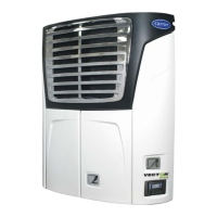
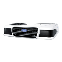
Overview of the Vector 8100 unit, its design, electrical power supply, and main sections (condensing and evaporator).
Details the components of the condensing section, including compressor, condenser coil, economizer, and associated controls.
Describes the evaporator coil, expansion valve, sensors, and other components located within the refrigerated compartment.
Explains the APX control system, its features like IntelliSet, DataLink, and describes key modules like PCM and Display Module.
Covers optional features such as Light Bar, Remote Switches, and Remote Panel for enhanced unit monitoring and control.
Provides technical specifications for the unit's compressor, including part number, displacement, and oil charge.
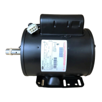
Details electrical specifications for components like the compressor motor, condenser fans, and evaporator fan motor.
Describes the main display unit, its keys, and how it shows box temperature, setpoint, and status information.
Provides step-by-step instructions for starting and stopping the refrigeration unit using the START/RUN-OFF switch.
Explains the Inspect Mode feature, used for safety during pre-trip inspections, which forces unit shutdown.
Details the IntelliSet feature for pre-selecting and naming unit settings for various products to optimize performance.
Describes the Pretrip function, a series of tests to check unit operation, and how to interpret results.
Guides users on how to adjust the unit's setpoint temperature using the display mounted keys.
Explains how to select and operate the unit in either Start-Stop or Continuous modes for power saving or consistent cooling.
Details the built-in DataLink data recorder, its capabilities for recording system information, and data downloading.
Provides instructions on how to view active alarms, clear them, and access the inactive alarm list.
Introduces temperature control concepts and describes the electrical sequence of operations for starting the unit.
Explains unit operation during startup, soft start, and the different modes like cooling, heating, and null.
Details how the APX Control System monitors temperatures and switches between cooling, heating, and null modes.
Covers the defrost cycle, including initiation methods, modes (Normal, Natural), and termination criteria.
Describes optional software overrides like Supply Air Limit Control and Temperature Range Lock for customized operation.
Outlines the four primary methods for interacting with the APX Control System: Driver, Technician, USB, and TRU-Tech.
Explains access and functions within Technician Mode, including hour meters, inactive alarms, and configuration settings.
Covers procedures for using USB devices for data transfer, software installation, and configuration file management.
Explains how to use TRU-Tech and TRU-View software for accessing and downloading data, programming, and configuration.
Details the procedure for replacing the main microprocessor, including pre-replacement steps, installation, and setup.
Lists common messages displayed in the MessageCenter, their descriptions, and related sections for more information.
Guides on how to interpret and troubleshoot alarms, including reviewing active and inactive alarm lists.
Provides detailed troubleshooting steps for various alarms, categorized by system component and issue type.
Troubleshooting steps for alarms related to high discharge pressure, A/C amps, battery voltage, and electrical faults.
Guidance for diagnosing issues with temperature sensors, communication errors, and input voltage problems.
Troubleshooting steps for alarms indicating maintenance is due, setpoint errors, or configuration issues.
Outlines the regular maintenance schedule required for optimal unit operation and longevity.
Details the pre-trip inspection procedures to be performed before each trip and at regular maintenance intervals.
Covers procedures for servicing the refrigerant system, including charge level checks, leak checking, and evacuation.
Provides steps for checking, adjusting, and adding refrigerant charge to the system for optimal performance.
Explains methods for leak checking the refrigeration system under various conditions, emphasizing safety.
Provides instructions for the removal and replacement of the compressor, including safety precautions.
Details service procedures for individual refrigerant system components like coils, valves, and sensors.
Covers service procedures for electrical components such as microprocessors, power modules, and contactors.
Provides instructions for replacing the main microprocessor module, ensuring software compatibility.
Details the procedure for removing and installing the Power Control Module, including torque specifications.
Guides on diagnosing and resolving issues related to the battery charger and its components.
Covers common problems and solutions for refrigeration and temperature control system malfunctions.
Troubleshooting steps for when the unit fails to cool, has insufficient cooling, or runs excessively.
Addresses problems related to heating function, termination of heating, and defrost cycle malfunctions.
Guides for diagnosing issues caused by abnormal pressures or restricted evaporator airflow.
Troubleshooting for malfunctions of key components like expansion valves, CSMV, and ECXV.
| Brand | Carrier TRANSICOLD |
|---|---|
| Model | VECTOR 8100 |
| Category | Refrigerator |
| Language | English |