2–9 62-11785
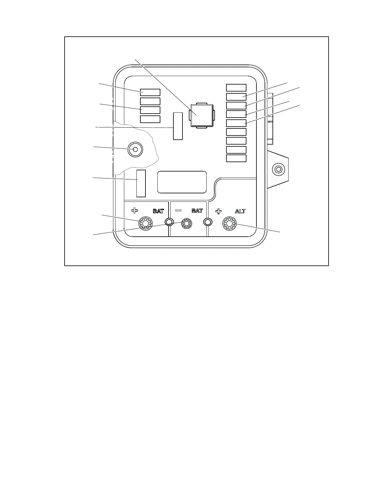
Figure 2.4 Power Control Module
1. Relay, Power Enable (PER)
2. Fuse (F1 = 5 amp), Module Logic Circuit and
Buzzer Power
3. Fuse (F3 = 5 amp), 2SVM & 3SVM Component
Actuation Power
4. Fuse (F5 = 30 amp), Power Enable Relay Contact
Power
5. Buzzer (B)
6. Fuse (F7 = 80 amp) Main Power
7. Battery Positive Connection (T1)
8. Battery Negative Connection (T2)
9. Battery Charger Output Connection (T3)
10. Fuse (F12 = 5 amp), Satellite Communications
Power
11. Fuse (F11 = 5 amp), Light Bar Power
12. Fuse (F10 = 20 amp), Main Microprocessor
Module Component Actuation Power
13. Fuse (F9 = 5 amp), Contactor Control Board
Component Actuation Power
F9
F5
F1
F3
F10
K1
F12
F11
12
13
11
10
9
4
2
1
6
7
3
8
5
F7

 Loading...
