5–17 62-11785
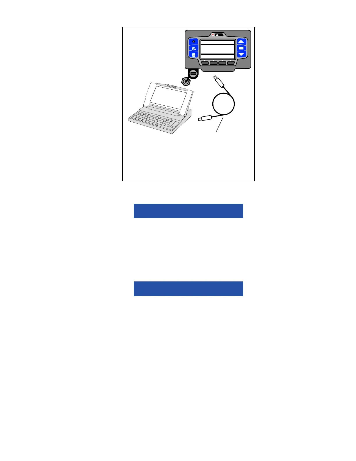
Figure 5.10 TRU-Tech/TRU-View Connection
5.5 MAIN MICROPROCESSOR REPLACEMENT / SETUP
Under no circumstances should a technician electrically probe the modules at any point, other
than the connector terminals where the harness attaches. Module components operate at
different voltage levels and at extremely low current levels. Improper use of voltmeters, jumper
wires, continuity testers, etc. could permanently damage the module.
Some main microprocessor inputs operate at voltage levels other than the conventional 12 VDC. These inputs
include but are not limited to the pressure transducers and temperature sensors. Under no circumstances should 12
VDC be applied at these connection points.
Electronic modules MUST be handled with care to prevent accidental damage or degradation
from electrical static discharge (ESD), contamination or abuse. Before touching a module,
touch your body and/or conductive tool being used to the frame to discharge ESD safely. All
electronics should be handled carefully and only held by edges of any exposed board. Care
should be taken when inserting/extracting connectors and components to avoid exerting
excessive stress on the board which could fracture small components nearby, resulting in
future failure of circuit.
When field diagnosis of a Carrier Transicold refrigeration unit determines that an APX main microprocessor is not
performing properly and must be replaced the replacement microprocessor must be setup for this unit and customer
by entering the required Configurations, Functional Parameters and DataLink data recorder settings.
If the replacement microprocessor is not loaded with the most recent software, it should be updated. If software is
loaded, it should be verified that it is the approved revision for this model.
When a module is replaced, software should be upgraded before switching the unit on. This will
ensure software compatibility of all modules.
PC–USB Service Cable. Carrier Transicold
Part number:
22–04253–01 = 20 foot/6.1 meter long)
22–04253–00 = 6 foot/1.8 meter long)
NOTE: An “off the shelf” USB to USB cable
will not provide the required communication.
PRESS = TO LOAD, OTHER TO EXIT
SOFTWARE INSTALL MENU
CURRENT SOFTWARE VERSION:
##.##.01
SOFTWARE ON USB: ##.##.02

 Loading...
