62-11785 8–32
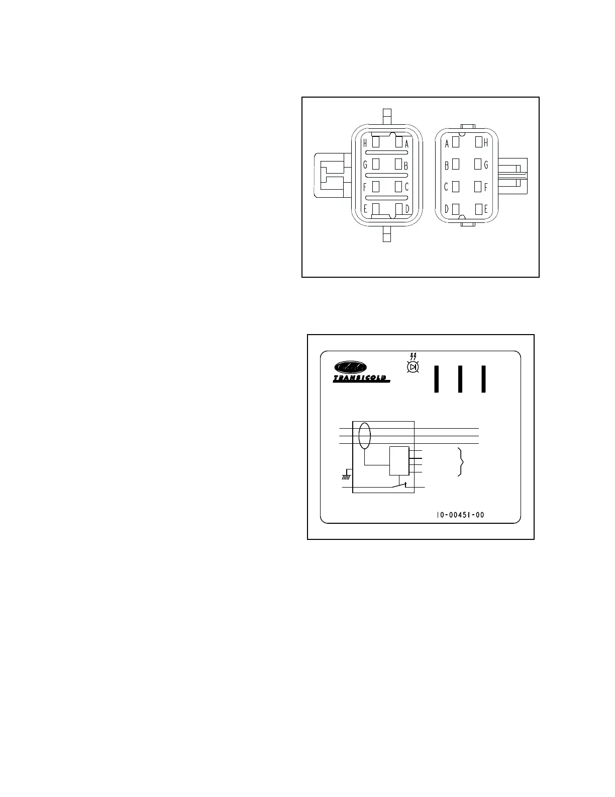
8.8.7 Light Bar
The light bar may be tested using a 12 VDC source.
1. Ensure unit will not start automatically by
placing the START/RUN-OFF switch in the OFF
position and removing the negative battery
cable. Disconnect the high voltage source and
lockout/tagout the receptacle.
2. Connect the ground (-) from the power source to
pin G on the light bar side of the connector.
3.
The green LED’s will illuminate when the 12
VDC side (+) of the power source is connected
to pin B.
4. With the connection as in the preceding steps (+
on pin B, and - on pin G), the amber LED’s will
illuminate when the power (+) from the power
source is also connected to pin H.
5.
Reinstall the negative battery cable, start unit
and run Pretrip to check operation
.
Figure 8.21 Light Bar Connections
8.8.8 Overload Ground Fault (OGF)
Operation
The OGF is designed to detect current overload and
fault to ground in the AC voltage circuits. The function
of the OGF is to shut down the power supply when
current is over 40 amp for 2 seconds, or leakage to
ground is more than 150mA.
Power, from HVB1K, energizes the OGF at terminal
+12 V. The module is grounded by the microprocessor
at the OV terminal through SP50.
This power also flows through the OGF normally
closed contacts and the S+ terminal through SP63 to
2CCB. If an overload or excessive leakage to ground
condition exists, the OGF contacts open to de-energize
and stop the flow of power to CCB1. Loss of power at
CCB1 activates alarm 00100 OVERLOAD/GROUND
FAULT.
Figure 8.22 Overload Ground Fault Connections
OGF Checkout Procedure
1. Check the FAULT LED on the module. If the LED is illuminated the module has activated and 12 VDC power
supply is correct. Perform a megohm test (refer to Section 8.8.6) to determine if a fault to ground exists.
This test will also help determine if an excessive current condition exists due to leakage to ground. Repair
wiring or components as required.
2. If
alarm 00100 OVERLOAD/GROUND FAULT
is present and the fault LED (on the module) is not illuminated,
it means that the module has detected an overcurrent. Verify the current readout on the unit data.
If current readings are not reading correctly, the current sensor may be at fault. Go to step 5 & 6 to check the
current sensor.
3. If a problem with the module is suspected, check for 12VDC power to the module at the +12V terminal and
ground at the OV terminal. Correct wiring as required. Reset module by placing the Main Power switch in the
OFF position and then back in the desired position. Check for 12 VDC at the S+ terminal. If LED is off and the
module normally closed connection is open, replace module.
4. If module is OK, check for 12 VDC at SP63.
A
H
E
F
G
D
C
B
LIGHT BAR
SIDE
CONTROL BOX
SIDE
A
H
E
F
G
D
C
B
GROUND
FAULT
S+ +12V OV
L1
L2
L3
BLUE
BROWN
ORANGE
BLACK
TO CURRENT
SENSORS
S+
OV
+12V

 Loading...
