Home
Carrier TRANSICOLD
Refrigerator
VECTOR 8100
Carrier TRANSICOLD VECTOR 8100 User Manual
5
of 1
of 1 rating
294 pages
Give review
Manual
Specs
To Next Page
To Next Page
To Previous Page
To Previous Page
Loading...
8–17
62-11785
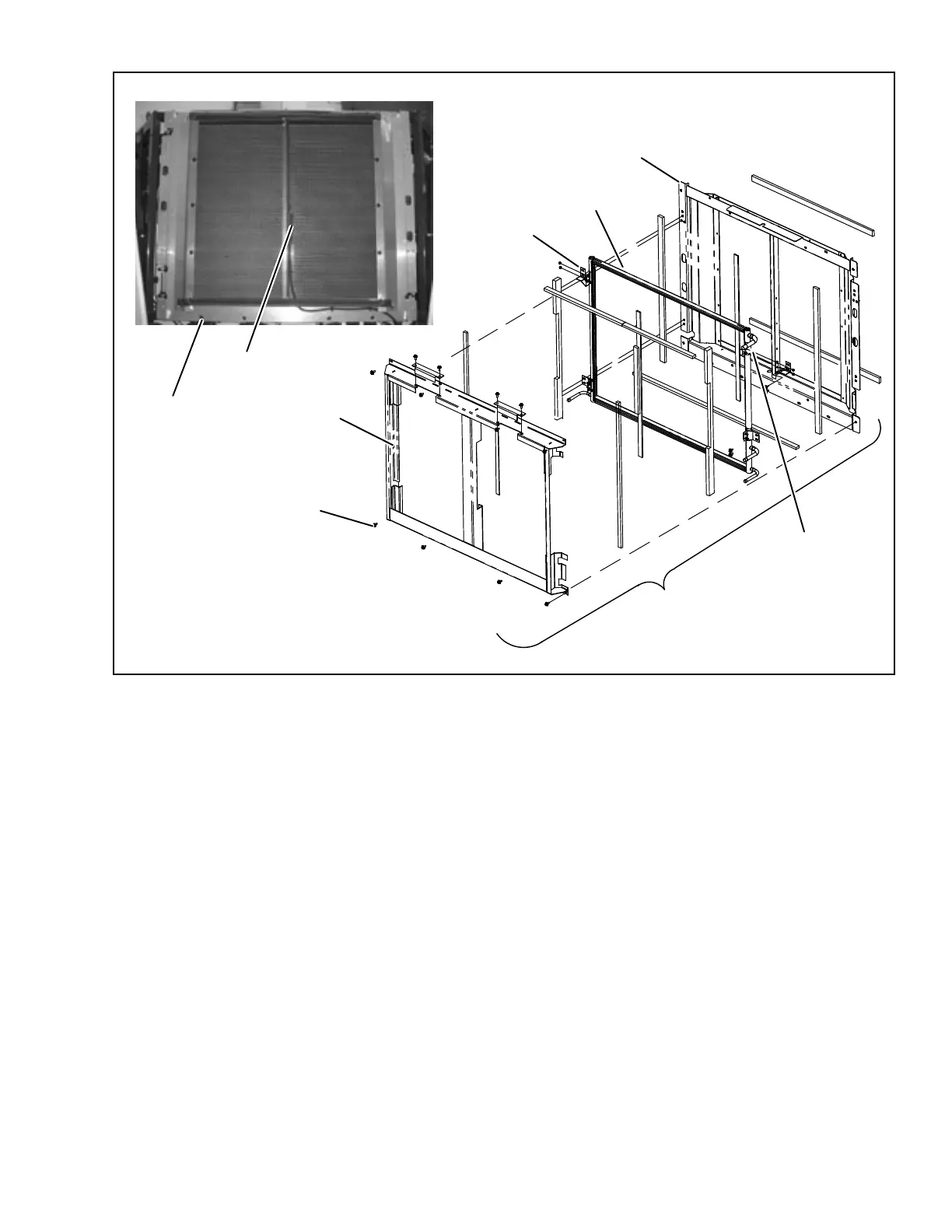
Figure 8.7
Condenser
Assembly
1.
Condenser Frame
Assembly
2.
V
enturi Frame
3.
Condenser Coil
4.
Condenser Frame
5.
Ambient
Air T
emperature Sensor (A
TT)
6.
Condenser Frame
Assembly Mounting Bolts
7.
Condenser Frame
Mounting Bolts
8.
Condenser Coil Mounting Brackets
3
5
4
6
7
8
1
2
NOTE: Inlet may be
lower on later design.
246
248
Table of Contents
Table of Contents
5
Safety Precautions
17
Safety Precautions Specific Warning, Caution, and Notice Statements
17
Figure 1.1 Lockout/Tagout
20
Safety Decals
24
Section 2 - Unit Description
29
Figure 8.13 Evaporator Expansion Valve
29
General Description
31
Introduction
31
Section 2 - Unit Description
31
Table 2-1 Model Chart
31
Table 2-2 Additional Support Manuals
31
Unit Description
31
Figure 2.1 Front View - Refrigeration System Components
32
Figure 2.2 Evaporator Section - Grille Removed
33
Figure 2.3 Control and Standby Boxes
34
Compressor Switches, Transducers and Sensors
35
Condenser Coil
35
Condensing Section
35
Economizer Circuit
35
Liquid Injection Solenoid Valve (LIV)
35
Ambient Air Temperature Sensor (AAT)
36
Compressor Suction Modulation Valve (CSMV)
36
Economizer Transducer and Sensor
36
Evaporator Expansion Valve (EVXV)
36
Evaporator Section
36
Filter-Drier
36
Receiver
36
Automatic Start-Stop
37
Evaporator Switches, Transducers and Sensors
37
Multiple Languages
37
System Operating Controls and Components
37
Component Description and Location
38
Special Features
38
Figure 2.4 Power Control Module
39
Figure 2.5 OGF Module
40
Figure 2.7 Light Bar
42
Light Bar
42
Options
42
Remote Switch(Es)
42
Remote Temperature Sensor
42
Compressor Data
43
Electrical Data
43
Refrigeration System Data
43
Remote Panel
43
2.10 Component Resistance & Current Draw Data
45
2.11 Safety Devices
45
2.12 Refrigeration Circuit During Cooling
45
Standard Mode
45
2.13 Heat and Defrost
46
Economized Mode
46
Liquid Injection Mode
46
Null Mode
46
Figure 2.8 Refrigeration Circuit Standard Mode
47
Figure 2.9 Refrigeration Circuit Economized Mode
48
Section 3 - Operation
49
Display
49
Operation
49
Figure 3.1 Display Module
51
Display Screens
52
Starting Unit
53
Inspect Mode
54
Intelliset
55
Pretrip
57
Changing Setpoint
60
Start-Stop Operation
61
Continuous Operation
62
3.10 Data Recorder
63
APX Control System Information
63
Data Recording
63
Data Downloading
64
Datalink Data Recorder Power-Up
64
3.11 Manual Defrost
66
3.12 Language Selection
67
3.13 Advanced User
68
3.14 Unit Data
69
Table 3-1 Unit Data
70
3.15 View Active Alarms
71
3.16 View Hour Meters
72
3.17 Functional Parameters
73
Table 3-2 Functional Parameters
73
3.18 Stopping Unit
76
3.19 Option - Datatrak
77
3.20 Emergency Bypass Mode
78
3.21 Remote Panel
79
Section 4 - Temperature Control
81
Introduction
81
Temperature Control
81
Sequence of Operation - Electrical
83
Operation
84
Soft Start (Bump Start)
84
Start-Stop Operation
84
Start-Up
84
Start-Stop Configuration
85
Stop Parameters
85
Re-Start Parameters
86
Continuous Operation
87
Perishable and Frozen Setpoint Ranges
87
Temperature Control
87
Temperature Determination
87
Cool Mode
88
Cool/Heat/Null Mode Switching Logic
88
Heat Mode
88
Null Mode
88
Defrost
89
Defrost Initiation
89
Defrost Modes
90
Defrost Termination
90
Supply Air Limit Control
91
User Selected Override Operation
91
Figure 4.1 Range Lock Settings - Non Overlapping
92
Temperature Range Lock 1 & 2
92
Figure 4.2 Range Lock Settings - Overlapping
93
Productshield
93
Cargo Protect Mode
95
CSMV Control Overrides
95
High Discharge Temperature
95
Preprogrammed Software Overrides
95
Section 5 - Control System Interface
97
Figure 5.1 Technician Mode
97
Figure 5.3 Inactive Alarms
97
Figure 5.5 Component Test Mode
97
Figure 5.9 Transferring Configuration Files
97
Interface Methods Technician Mode
97
Service Mode
97
Tru-Tech & Tru-View
97
Usb Memory Devices
97
Technician Mode
99
Figure 5.2 Technician Hour Meters
100
Technician Hour Meters
100
Inactive Alarms
101
Configuration Settings
103
Figure 5.4 Setting Configurations
103
Component Test Mode
105
Data Transfer USB Memory Device
107
Usb Memory Devices
107
Figure 5.6 PC Mode
108
PC Mode
108
Downloading Data Files
110
Figure 5.7 Downloading Data Files
110
Figure 5.8 Installing Software
111
Installing Software
111
Transferring Configuration Files
113
Connecting Computer and APX Control System
114
TRU-Tech
114
Tru-Tech & Tru-View
114
TRU-View
114
Figure 5.10 TRU-Tech/Tru-View Connection
115
Main Microprocessor Replacement / Setup
115
Main Microprocessor Module Replacement
116
Pre-Replacement Steps
116
Main Microprocessor Setup
117
Configurations Using Display Mounted Keys
118
Datalink Data Recorder Via TRU-Tech
118
Functional Parameters Via Display Mounted Keys
118
System Final Checkout
118
Table 5-1 Configuration Settings
128
Messagecenter Messages
131
Table 6-1 Messagecenter MESSAGES
131
Section 7 - Alarm Troubleshooting
135
Figure 2.6 Display Module
136
Alarm Troubleshooting
139
Introduction
139
Notes
140
00013 High Discharge Pressure
141
Alarms
141
High Discharge Pressure
141
00015 Battery Voltage too High
142
Battery Voltage too High
142
High A/C Amps
142
00016 Battery Voltage too Low
143
Battery Voltage too Low
143
00017 High Comp Discharge Temp
144
High Comp Discharge Temp
144
00018 Low Refrigerant Pressure
145
Low Refrigerant Pressure
145
00020 Maximum Compressor Alarms
146
Maximum Compressor Alarms
146
00022 Low Suction Superheat
147
Low Suction Superheat
147
00023 A/C Current over Limit
148
A/C Current over Limit
148
00024 Compression Ratio Exceeded
150
Compression Ratio Exceeded
150
00027 High Suction Pressure
151
High Suction Pressure
151
00028 Check Refrigeration System
152
00030 Failed to Run Minimum Time
152
Check Refrigeration System
152
Failed to Run Minimum Time
152
00051 Alternator (Battery Charger) Not Charging
153
Alternator (Battery Charger) Not Charging
153
00053 Box Temp Out-Of-Range
154
Box Temp Out-Of-Range
154
00054 Defrost Not Complete
155
Defrost Not Complete
155
00055 Check Defrost Air Switch
156
Check Defrost Air Switch
156
00057 Check Remote Switch 1 (Rems1)
157
Check Remote Switch 1 (Rems1)
157
00058 Check Remote Switch 2 (Rems2)
158
00059 DATALOGGER (Datalink Data Recorder) NOT RECORDING
159
00060 DATALOGGER (Datalink Data Recorder) TIME WRONG
159
00061 Door Open (Ds1)
160
Door Open (Ds1)
160
00073 No Power-Check Power Cord
161
No Power-Check Power Cord
161
Phase Reversed
162
00075 Comp Motor Overload
163
Comp Motor Overload
163
00076 Condenser Motor Overheated
164
Condenser Motor Overheated
164
00077 Evap Motor Overheated
166
Evap Motor Overheated
166
00084 Check Remote Alarm Light
167
00093 Check Startup Buzzer
167
Check Remote Alarm Light
167
Check Startup Buzzer
167
00094 Check Comp Contactor 1
168
Check Cdcon1 Coil
168
00098 Check High Temp Thermostat
169
Check High Temp Thermostat
169
00100 Overload/Ground Fault
170
Overload/Ground Fault
170
Check 1Evcon Coil
171
Check Liv Circuit
171
00121 Check Ambient Air Sensor
172
00122 Check Return Air Sensor
172
Check Ambient Air Sensor
172
Check Return Air Sensor
172
00123 Check Supply Air Sensor
173
Check Supply Air Sensor
173
00124 Check Defrost Term 1 Sensor
174
Check Defrost Term 1 Sensor
174
00125 Check Comp Discharge Sensor
175
00127 Check Suction Temp Sensor
175
Check Comp Discharge Sensor
175
Check Suction Temp Sensor
175
00131 Check Evap Temp Sensor
176
Check Evap Temp Sensor
176
00133 Check Remote Temp Sensor 1
177
00134 Check Remote Temp Sensor 2
177
00135 Check Remote Temp Sensor 3
177
P00141 Pretrip Stopped by User
178
P00153 Check Return Air Sensor
178
P00154 Check Supply Air Sensor
178
P00157 Check Battery Current
179
P00158 Check Ambient Air Sensor
179
P00159 Check Defrost Term 1 Sensor
179
P00160 Check Discharge Temp Sensor
180
P00161 Check Suction Temp Sensor
180
P00170 Check Liv Circuit
180
P00173 Check Economizer
180
P00177 Check Exv (Evxv) Superheat
181
P00179 Check Liv
181
P00180 Check Suction Mod Valve
182
P00186 Check Evap Outlet Temp
182
P00187 Check Heater 1 Circuit
183
P00188 Check Heater 2 Circuit
185
P00189 Check Evaporator Fan Motor
187
P00190 Check Condenser Fan Motor
189
P00206 Check Condenser Fan Circuit
190
P00207 Check Compressor Contact Circ
190
P00209 Check Standby Cont Circuit
191
00224 Standby Maintenance Due
192
00225 General Maintenance Due
192
00226 Service Soon-Pm #1 Due
192
General Maintenance Due
192
Service Soon-Pm #1 Due
192
Standby Maintenance Due
192
00227 Service Soon-Pm #2 Due
193
00228 Service Soon-Pm #3 Due
193
Service Soon-Pm #2 Due
193
Service Soon-Pm #3 Due
193
00229 Service Soon-Pm #4 Due
194
00230 Service Soon-Pm #5 Due
194
Service Soon-Pm #4 Due
194
Service Soon-Pm #5 Due
194
Model # Error
195
Setpoint Error
195
00237 Function Parameters Error
196
Function Parameters Error
196
00238 Configurations Error
197
Configurations Error
197
00245 Cannot Save Setting
198
00246 Eeprom Write Failure
198
Cannot Save Setting
198
Eeprom Write Failure
198
00248 Config Mode / Hp2 Error
199
Config Mode / Hp2 Error
199
00255 Microprocessor Error
200
02001 Rear Panel Shutdown
200
Microprocessor Error
200
Rear Panel Shutdown
200
Update Software
200
02002 Low Discharge Superheat
201
Low Discharge Superheat
201
Display Module Error
202
04002 High Economizer Superheat
203
High Economizer Superheat
203
No Setpoint Change
203
Bad F9 Fuse
204
Power Enable Relay Fuse Alarm
204
Bad F10 Fuse
205
Bad F3 Fuse
205
05009 Check Standby Contactor One (Pscon)
206
Check Standby Contactor One (Pscon)
206
05010 Check Standby Contactor Two (Pscon2)
207
Check Standby Contactor Two (Pscon2)
207
05016 Check Remote Amber Light
208
05018 Check Power Enable Control
208
Check Remote Amber Light
208
Check Cdcon2 Coil
209
Check Htr Cntr One
210
Check Htr Cntr Two
211
06000 Condenser Motor2 Overheated
212
07000 Economizer Temp Sensor
213
Check Light Bar
213
07001 Economizer Press Sensor
214
07006 Suction Pressure Sensor
214
07008 Check Redundant Return Air Sensor (Rat2)
215
07009 Return Air Sensors out of Range (Rat & Rat2)
215
20100 No Comm from Micro to Display
216
P11000 Check Condenser Fan Motor 2
216
P13000 Check Condenser Fan 2 Circuit
216
20101 No Comm from Micro to Remote Display
217
21100 No Comm from any Board to Main Micro
218
22100 No Comm from Micro to Inpbd1
218
22101 Sensor Input Voltage Low Inp1
219
22102 Sensor Input Voltage High Inp1
220
22103 Input Lost Configuration
220
23100 No Comm from Micro to Outpbd1
221
23101 Output Lost Configuration
221
24100 No Comm from Micro to Ccb1
222
24101 Sensor Input Voltage Low Ccb1
222
24102 Sensor Input Voltage High Ccb1
223
24200 No Comm from Micro to Ccb2
223
24201 Sensor Input Voltage Low Ccb2
224
24202 Sensor Input Voltage High Ccb2
224
25100 No Comm from Micro to Stp1
225
Over Current Stp1
225
25102 Check Input Voltage Stp1
226
25200 No Comm from Micro to Stp2
226
25202 Check Input Voltage Stp2
227
27200 No Comm from Micro to Optional Comm Module
227
Over Current Stp2
227
28002 No Comm from Door Switch
228
Invalid Door Switch
228
Section 8 - Service
229
Compressor Suction Modulation Valve (CSMV)
229
Figure 8.4 Refrigerant System Service
229
Scheduled Maintenance
231
Section Layout
231
Pre-Trip Inspection
232
Table 8-1 Maintenance Schedule
232
External Surface Service
233
Figure 8.1 Grille Insert Removal and Door Latch Maintenance
233
Figure 8.2 Surround Removal
233
Door Latch Maintenance and Replacement
234
Figure 8.3 Door Latch Cable Removal
234
Refrigerant System Service Connections
235
Servicing the Refrigerant Charge
235
Leak Checking
238
Evacuation and Dehydration
241
Compressor Service
243
Figure 8.5 Compressor Kit
243
Figure 8.6 Compressor Plug Retaining Clip
244
Evaporator Coil
245
Refrigerant System Component Service
245
Condenser Coil
246
Figure 8.7 Condenser Assembly
247
Economizer Heat Exchanger
248
Filter-Drier
248
Replacing Receiver Sight Glass or Fusible Plug
248
Figure 8.8 Economizer Section
249
Figure 8.9 Stepper Test Harness
249
Stepper Test Harness
249
Figure 8.10 Suction Modulation Valve (CSMV)
250
Figure 8.11 CSMV Coil
250
Expansion Valves, EVXV & ECXV
252
Figure 8.12 Evaporator Expansion Valve
252
Table 8-2 Expansion Valve Connections
252
Liquid Injection Solenoid Valve
254
Figure 8.14 Solenoid Valve (LIV)
255
Figure 8.15 Testing High Pressure Switch
255
High Pressure Switch
255
Defrost Air Switch
256
Figure 8.16 Defrost Air Switch Test Setup
256
Pressure Transducers
256
Electrical System Componentservice
258
Figure 8.17 Power Control Module
258
Main Microprocessor Module (MM)
258
Power Control Module (PCM)
258
Contactor Control Board (CCB)
259
Display Module (DM)
259
Stepper Valve Module (SVM)
259
Megohmmeter Test Procedure
261
Figure 8.21 Light Bar Connections
262
Figure 8.22 Overload Ground Fault Connections
262
Light Bar
262
Overload Ground Fault (OGF)
262
Evaporator Blower & Motor
263
Evaporator Heaters
263
Figure 8.23 Evaporator Blower Assembly
264
Condenser Fan Assemblies
265
Figure 8.24 Condenser Fan Assembly
265
Battery Charger (BTYC)
266
Compressor Discharge Temperature Sensor
266
Figure 8.25 Compressor Discharge Temperature Sensor
266
Table 8-3 Sensor Resistance
267
Temperature Sensor Checkout
267
Table 8-4 Sensor Resistance (CDTS)
268
Table 8-5 Temperature Pressure Chart
269
Table 8-6 Compressor Discharge
270
Table 8-7 Compressor Suction Pressure Transducer Pressure/Voltage
270
Table 8-8 Current Sensor Millivolt Output Vs Current Sensed
270
Battery Charger
273
Refrigeration / Temperature Control
273
Unit Troubleshooting
273
Unit will Not Cool
275
No Evaporator Air Flow or Restricted Air Flow
277
Abnormal Discharge Temperature (High)
278
Compressor Suction Modulation Valve (CSMV) Malfunction
278
Economizer Valve (ECXV) Malfunction
278
Expansion Valve (EVXV) Malfunction
278
10.1 Harness Connector Wiring
279
Wiring
279
10.2 Harness Connectors, Control Box
285
10.3 Wiring Schematic
285
Index
289
5
Based on 1 rating
Ask a question
Give review
Questions and Answers:
Need help?
Do you have a question about the Carrier TRANSICOLD VECTOR 8100 and is the answer not in the manual?
Ask a question
Carrier TRANSICOLD VECTOR 8100 Specifications
General
Brand
Carrier TRANSICOLD
Model
VECTOR 8100
Category
Refrigerator
Language
English
Related product manuals
PrimeLINE 69NT40-571-001
186 pages
PrimeLINE 69NT40-571-199
186 pages
eSolutions Supra 60 Series
39 pages
Carrier TRANSICOLD Supra 560
42 pages
eSolutions Supra 960
39 pages
Carrier TRANSICOLD Supra 860
42 pages

 Loading...
