62-11785 2–10
b. Main Microprocessor Module
The main microprocessor module (MM) houses the main system microprocessor. The module is totally self
contained and does not contain any serviceable components.
c. SVM Module
The stepper valve module (SVM) houses the CSMV, EVXV & ECXV operating microprocessor. The module is
totally self contained and does not contain any serviceable components.
d. Microprocessor Status LED
Microprocessor activity within the main microprocessor SVM Module or contractor control boards can be
determined by observing the status LED’s. Module LED’s are located just to the right of the module bar code while
contactor control board LED’S are visible through small openings in the bottom mounting bracket.
An LED will:
• blink, green in color, once per second to indicate
that the microprocessor is operating correctly
• be off indicating no power to the module
• be on steadily, green in color, to indicate that the
microprocessor is not communicating (check
CAN bus)
• be on steadily, red in color, to indicate an internal
failure or loss of software.
e. Contactor Control Boards
The contactor control boards (1CCB & 2CCB - see Figure 2.3) are slave boards that contain the necessary
software to control the contactors in accordance with the unit model programmed into the main microprocessor.
The boards communicate with the control system through the CAN network.
f. AC Current Sensor
The current sensor (CT1, CT2 & CT3 - Item 13, Figure 2.3) provides a reading of each individual AC line current
draw (amps) to the main microprocessor through the CAN bus from 1CCB at terminals 1CCB-12, -34, -10 & -31
(see schematic diagram, Section 10.3).
g. High Voltage Transformer (HVT)
The high voltage transformer (See Figure 2.3) provides a reading of line voltage to the main microprocessor
through the CAN bus from 1CCB at terminals 1CCB-19 & -35 (see schematic diagram, Section 10.3).
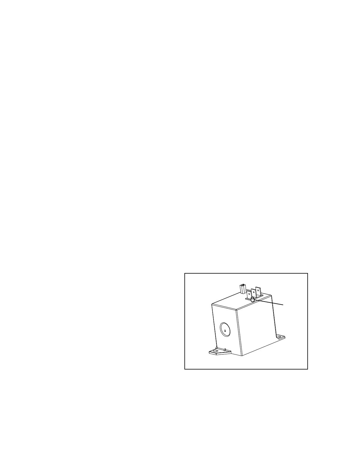
h.Overload Ground Fault Module (OGF)
The OGF, see Figure 2.5, is located in the control box
(Figure 2.3). The module has two electrical safety fea-
tures:
1. Overload protection.
2. Ground Fault (Leakage).
In each case, the 00100 OVERLOAD/GROUND
FAULT alarm is activated and the unit shuts down.
When ground leakage is detected, the red LED on the
OGF module will be on continuously.
Figure 2.5 OGF Module

 Loading...
