62-11785 2–12
k. Display Module Keys
• ALARM - The ALARM key allows viewing of the alarms stored in the system.
• UP ARROW and DOWN ARROW - These keys allow scrolling through the selections presented.
• EQUAL (ENTER) - The EQUAL key is used to confirm a selection and lock it into memory.
• START-STOP/CONTINUOUS - Pressing this key toggles between Start-Stop and Continuous Operation.
• DEFROST - Used to manually initiate a defrost cycle when the required conditions are met.
• MENU - Pressing the MENU key displays the various soft keys in the MessageCenter. The selections
offered are dependent on the operator’s status: Driver, Advanced User or Technician. Refer to Section 3 for
Driver & Advance User mode and Section 5 for Technician mode menu selection descriptions.
• The USB Interface Port - Used for installing software updates, options, configurations, functional parame-
ters and downloading of data from the Data Link data recorder.
2.6 OPTIONS
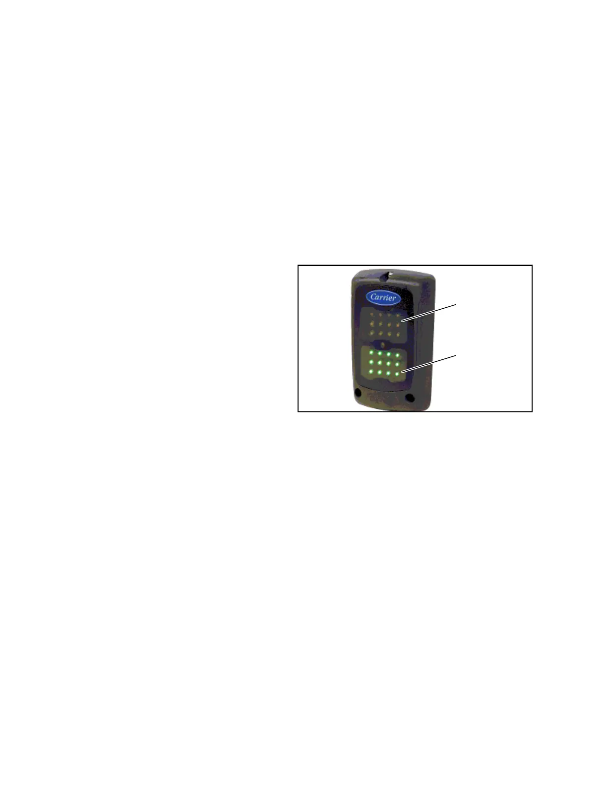
2.6.1 Light Bar
The Light Bar is an external indicator light which can be
seen in the driver’s rear view mirror from the cab of the
tractor. The green LED indicates “STATUS OK”. The
amber LED indicates “CHECK UNIT”. The amber light
is illuminated when the control system illuminates the
alarm light. Alarms can be read on the display.
Figure 2.7 Light Bar
2.6.2 Remote Switch(es)
The unit is provisioned to connect remote switches (DS/REMS1/REMS2) directly to the control system through the
REM connector to the SVM.
• Two types of switches may be used:
1. A switch with contacts that are open when the switch is activated.
2. A switch with contacts that are closed when the switch is activated.
• Three Configurations are available for each switch.
1. Activate an alarm only while the switch is activated.
2. Activate an alarm and shut the unit down while the switch is activated. The unit will remain shut down for a mini-
mum of 3 minutes under this setting.
3. Record the switch activation in the DataLink data recorder.
• If configured to shut the unit an additional choice will be available. The additional choice allows the unit to be
set so that the configured action will always take place OR the configured action will only take place when
the ambient temperature is below a certain temperature. For example, if the shutdown temperature choice is
set to 77°F (25°C) the unit will only shutdown if the ambient temperature is below 77°F (25°C).
• Additionally a Functional Parameter “override” setting will be available for each switch configured to shut the
unit down. The Functional Parameter may be set to “YES” or “NO”. If the Parameter is set to “NO” the config-
ured action will not be overridden. If the Parameter is set to “YES”, the alarm will be activated but the unit will
not shutdown.
2.6.3 Remote Temperature Sensor
The unit is provisioned to connect remote temperature sensors (REMSN1, REMSN2 & REMSN3) through the REM
connector to the second contactor control board (2CCB).

 Loading...
