8–25 62-11785
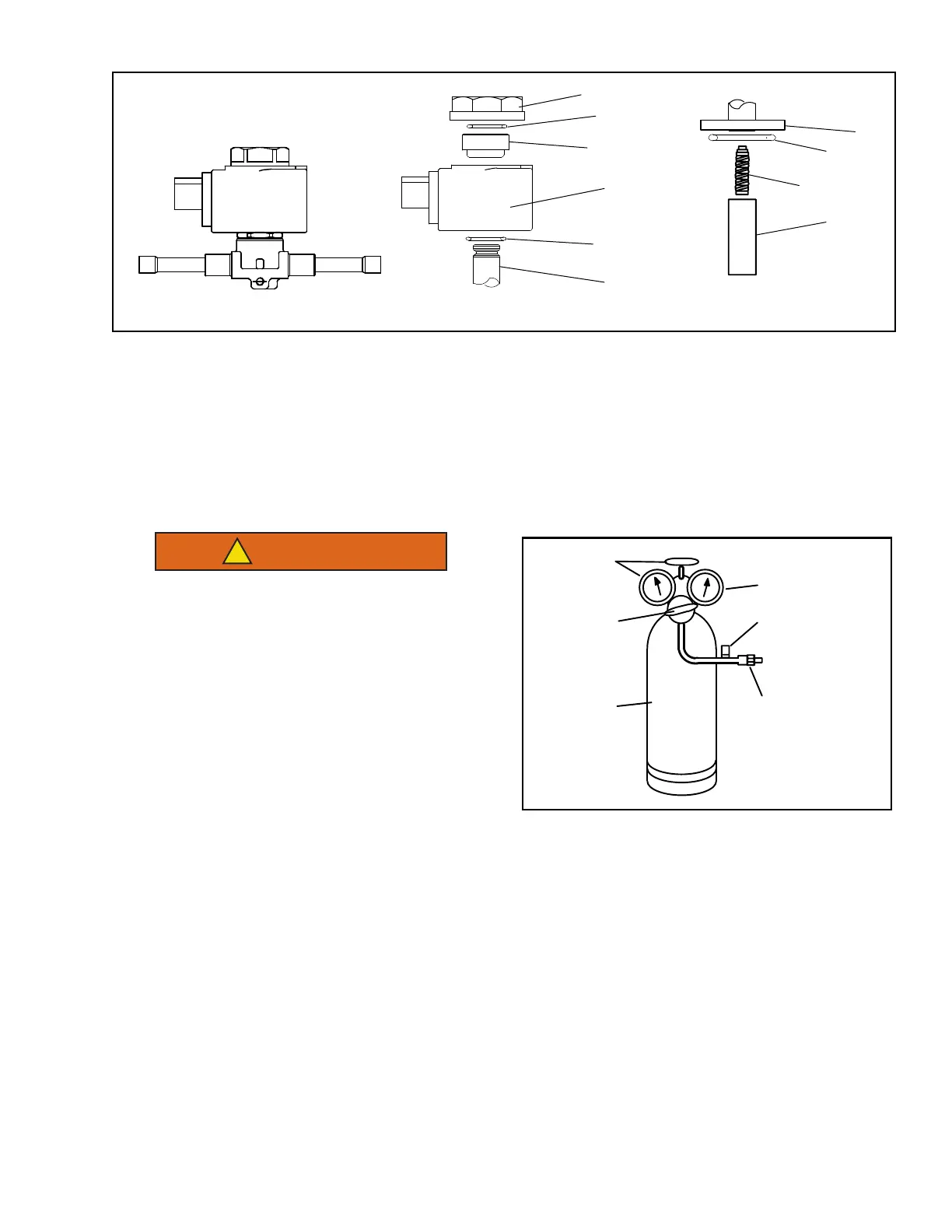
Figure 8.14 Solenoid Valve (LIV)
1. Locking Nut
2. Upper O-Ring
3. Threaded Collar
4. Coil
5. Lower O-Ring
6. Armature Tube
7. Internal O-Ring
8. Spring6
9. Armature
- - - - -
8.7.10 High Pressure Switch
a. Checking High Pressure Switch
Do not use a nitrogen cylinder without a
pressure regulator. Cylinder pressure is
approximately 2350 PSIG (160 bar). Do
not use oxygen in or near a refrigerant
system as an explosion may occur. (See
Figure 8.15
.)
1. Remove switch as outlined in preceding section.
2. Connect ohmmeter or continuity light across
switch terminals. Ohmmeter will indicate
resistance and continuity light will be illuminated if
switch closed after relieving pressure.
Figure 8.15 Testing High Pressure Switch
3. Connect switch to a cylinder of dry nitrogen, see
Figure 8.15
.
4. Set nitrogen pressure regulator higher than open setting for switch being tested. For pressure switch settings
refer to
Section 2.8
.
5. Close valve on cylinder and open bleed-off valve.
6. Open cylinder valve. Slowly close bleed-off valve and increase pressure until the switch opens. If light is used,
light will go out and if an ohmmeter is used, the meter will indicate open. Close cylinder valve. Slowly open
bleed-off valve (to decrease pressure) until switch closes (light will illuminate or ohmmeter will indicate open).
b. Replacing High Pressure Switch
1. Pump down the compressor. Refer to
Section 8.5.2
.
2. Disconnect wiring from switch, and remove switch.
3. Install switch after verifying switch settings. (Refer to following step b.)
4. Leak check, evacuate & dehydrate, and charge system as required. Refer to
Section 8.5.2
,
Section 8.5.3
&
Section 8.5.4
.
COIL ASSEMBLY INTERNAL COMPONENTSLIQUID INJECTION VALVE
Cylinder Valve
and Gauge
Pressure
Regulator
Nitrogen
Cylinder
Pressure Gauge
0 to 500 PSIG
(0 to 27.2 bar)
Bleed-Off
Valve
Switch

 Loading...
