EasyManua.ls Logo

Carrier 06E - Service Manual

Carrier 06E
20 pages
Print Icon
To Next Page IconTo Next Page
Loading...
Manufacturer reserves the right to discontinue, or change at any time, specifications or designs without notice and without incurring obligations.
PC 802 Catalog No. 530-607 Printed in U.S.A. Form 06/07E-2SI Pg 1 7-02 Replaces: 06/07E-1SI
Book 2244
Tab 1b2a2b3a
Installation, Start-Up and
Service Instructions
Hermetic, Water-Cooled
CONTENTS
Page
SAFETY CONSIDERATIONS
. . . . . . . . . . . . . . . . . . . . . . 1
INSTALLATION
. . . . . . . . . . . . . . . . . . . . . . . . . . . . . . . . . 1-6
Receive and Inspect Unit
. . . . . . . . . . . . . . . . . . . . . . . . . 1
Place Unit in Position
. . . . . . . . . . . . . . . . . . . . . . . . . . . . 1
Check Compressor Mounting
. . . . . . . . . . . . . . . . . . . . 1
Piping Connections
. . . . . . . . . . . . . . . . . . . . . . . . . . . . . . 2
Electrical Connections
. . . . . . . . . . . . . . . . . . . . . . . . . . . 2
PRE-START-UP
. . . . . . . . . . . . . . . . . . . . . . . . . . . . . . . . . .7,8
Evacuate, Dehydrate, and Leak Test
. . . . . . . . . . . . . . 7
Oil Charge
. . . . . . . . . . . . . . . . . . . . . . . . . . . . . . . . . . . . . . . . 7
START-UP
. . . . . . . . . . . . . . . . . . . . . . . . . . . . . . . . . . . . . . . . 8
Start Compressor
. . . . . . . . . . . . . . . . . . . . . . . . . . . . . . . . 8
Timer Functions
. . . . . . . . . . . . . . . . . . . . . . . . . . . . . . . . . . 8
SERVICE
. . . . . . . . . . . . . . . . . . . . . . . . . . . . . . . . . . . . . . 9-18
Protection Devices
. . . . . . . . . . . . . . . . . . . . . . . . . . . . . . . 9
Compressor Thermal Protection
. . . . . . . . . . . . . . . . . 9
Capacity Control System
. . . . . . . . . . . . . . . . . . . . . . . . . 9
Removing, Inspecting and Replacing
Components
. . . . . . . . . . . . . . . . . . . . . . . . . . . . . . . . . . 10
Lubrication System
. . . . . . . . . . . . . . . . . . . . . . . . . . . . . 13
Cylinder Heads
. . . . . . . . . . . . . . . . . . . . . . . . . . . . . . . . . . 14
Pressure Relief Valve
. . . . . . . . . . . . . . . . . . . . . . . . . . . . 14
Suction and Discharge Valve Plate Assembly
. . . 14
Terminal Plate Assembly
. . . . . . . . . . . . . . . . . . . . . . . . 14
Compressor Running Gear Removal
. . . . . . . . . . . . 14
Compressor Running Gear Replacement
. . . . . . . . 15
Motor Removal
. . . . . . . . . . . . . . . . . . . . . . . . . . . . . . . . . . 16
Motor Replacement
. . . . . . . . . . . . . . . . . . . . . . . . . . . . . 16
Motor Burnout (Clean-Up Procedure)
. . . . . . . . . . . . 17
Condenser Maintenance
. . . . . . . . . . . . . . . . . . . . . . . . 17
SAFETY CONSIDERATIONS
Installing, starting up, and servicing this equipment can be
hazardous due to system pressures, electrical components, and
equipment location (roofs, elevated structures, etc.). Only
trained, qualified installers and service mechanics should
install, start up, and service this equipment.
When working on the equipment, observe precautions in the
literature, tags, stickers and labels attached to the equipment,
and other safety precautions that apply. Follow all safety codes.
Wear safety glasses and work gloves. Use care when handling,
rigging, and setting bulky equipment.
INSTALLATION
Receive and Inspect Unit
Inspect shipment for
damage. File claim with the shipping company if shipment is
damaged or parts are missing.
Local water conditions can cause excessive fouling or
pitting of condenser tubes. If such conditions are anticipated, a
water treatment analysis is recommended. Refer to Carrier
System Design Manual, Part 5, for general water conditioning
information.
Place Unit in Position
Locate unit on floor in a
well-ventilated area. Install unit where it will be warmer than
conditioned area. Position it to allow sufficient space for refrig-
erant and water connections and to service compressor. Allow
space at one end of condenser for tube cleaning or replacement.
Place unit so suction and discharge valves can be easily
reached and so oil level can be checked.
Make provision in piping layout to drain and vent condenser
if system is to be shut down in winter.
Level unit and bolt firmly to foundation.
Check Compressor Mounting —
Loosen compres-
sor mounting bolts and remove shipping blocks from under
compressor. Tighten all 4 bolts on compressor. Loosen each
bolt just enough until the flanged washer can be moved
sideways with finger pressure. See Fig. 1.
NOTE: Be sure that compressor floats freely on mounting
springs.
Electrical shock can cause personal injury and even death.
Be sure power to equipment is shut off before installing or
servicing this equipment. There may be more than one dis-
connect. Tag disconnect(s) to alert others not to turn power
on until work is completed.
06E,07E
Compressors and Condensing Units
SELF-LOCKING
BOLT
SNUBBER FLANGED
WASHER
NEOPRENE
SNUBBER
COMPRESSOR FOOT
ISOLATION SPRING
Fig. 1 — Compressor Mounting
Question and Answer IconNeed help?

Do you have a question about the Carrier 06E and is the answer not in the manual?

Summary

Safety Considerations

General Safety Precautions

Emphasizes the need for trained personnel and adherence to safety codes, including wearing safety glasses and gloves.

Electrical Hazard Warning

Warns of electrical shock hazard and the necessity of shutting off power before installation or servicing.

Installation

Pre-Start-Up

Evacuate, Dehydrate, and Leak Test

Describes the process for ensuring the refrigerant system is leak-free and properly dehydrated using specified methods.

Oil Charge

Guidance on checking and adding approved compressor oil to the correct level in the crankcase.

Start-Up

Start Compressor

Procedure for initiating the compressor start sequence, checking oil pressure, and verifying oil level after operation.

Timer Functions

Explanation of the timer's role in compressor start delays, crankcase heater deactivation, and oil pressure switch bypass.

Service

Protection Devices

Details on how to check the high-pressure, low-pressure, and oil pressure switches and their settings.

Overview

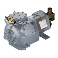
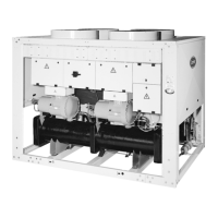
The Carrier 06E,07E Compressors and Condensing Units are designed for refrigeration and air conditioning applications, featuring hermetic, water-cooled operation. These units require careful installation, start-up, and regular service to ensure optimal performance and longevity.

Function Description

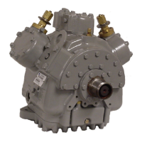
The core function of these units is to compress refrigerant, facilitating heat transfer in refrigeration and air conditioning systems. The 06E and 07E models are hermetic, meaning the compressor and motor are sealed within a single housing, preventing refrigerant leaks and contamination. The water-cooled design utilizes water to dissipate heat from the condenser, making them suitable for applications where air-cooling is less efficient or impractical.

The compressors are equipped with a capacity control system, which allows for efficient operation under varying load conditions. This system typically involves capacity control valves that regulate the number of active cylinders, thereby adjusting the compressor's output. For instance, the suction cutoff unloader operation, as described, allows the compressor to run fully loaded when suction pressure is high and unload cylinders when suction pressure drops below a set point. This mechanism helps maintain system efficiency and prevents short cycling.

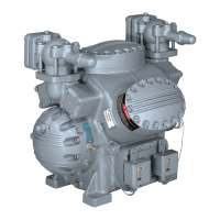
Protection devices are integrated to safeguard the compressor from abnormal operating conditions. These include high-pressure and low-pressure switches, which shut down the compressor if pressures exceed or fall below safe limits. An oil pressure switch (OPS) monitors the oil pressure differential, protecting against loss of lubrication. A discharge temperature sensor provides thermal protection, de-energizing the compressor if the discharge temperature becomes excessively high. The Time Guard® control prevents short cycling, further extending the life of the compressor.

Usage Features

Proper installation is crucial for the safe and efficient operation of the 06E,07E units. This involves carefully receiving and inspecting the unit for any shipping damage, and then positioning it in a well-ventilated area that allows sufficient space for refrigerant and water connections, as well as for future servicing. The unit must be leveled and bolted firmly to a foundation to minimize vibration and ensure stable operation. Compressor mounting bolts should be loosened to remove shipping blocks and then re-tightened to allow the compressor to float freely on its mounting springs, which helps absorb vibrations.

Piping connections for water supply and return lines, as well as refrigerant liquid and suction lines, must be made according to local codes and Carrier's System Design Manual. Special attention is required during soldering or brazing to prevent heat damage to valves. A solenoid valve is necessary for single pumpout control, and a filter drier of adequate size should be installed in the liquid line. Provision for draining and venting the condenser is essential, especially if the system is to be shut down in winter.

Electrical connections must comply with local and national codes. It is critical to ensure that the 3-phase supply voltage has an imbalance of no more than 2% to prevent motor damage and voiding the warranty. A branch circuit fused disconnect of adequate size must be installed within sight and readily accessible from the unit. Control circuit power supply (115 volts for 60 Hz units, 230 volts for 50 Hz units) is also required.

Before start-up, the entire refrigerant system must be evacuated, dehydrated, and leak tested using approved methods. The system should be charged to a clear sight glass, with additional refrigerant added for subcooler coils in air-cooled applications. The units are factory charged with oil, but the oil level must be checked and adjusted as needed to be within 1/8 to 3/8 of the bull's-eye during steady operation. Only Carrier-approved compressor oil should be used, and reused or atmosphere-exposed oil must be avoided.

Start-up procedures involve energizing the crankcase heater at least 24 hours prior to starting, checking oil level, opening water supply and liquid line valves, and starting the evaporator fan or chilled water pump. The compressor start is controlled by a timer, which introduces delays for time guard, part-winding start, oil pressure bypass, and low-pressure switch bypass, optimizing the start-up sequence and protecting the compressor.

Maintenance Features

Regular maintenance is essential for the long-term reliability of the 06E,07E units. This includes inspecting and servicing various components as described in the manual.

Compressor Components:

  • Cylinder Heads: These should be disassembled by removing cap screws and prying up on side lifting tabs. Inspection for warping, cracks, and gasket damage is crucial. When replacing, new gaskets must be used, and cap screws torqued to specifications.
  • Pressure Relief Valve: Located in the center cylinder bank (6-cylinder compressors) or under the discharge service valve (4-cylinder compressors), this internal safety device relieves excessive refrigerant pressure. It should be checked for leaks or evidence of having opened due to excessive pressure and replaced if defective.
  • Suction and Discharge Valve Plate Assembly: Leak testing for discharge valves is performed by pumping down the compressor and observing pressure equalization. If a discharge valve leaks, pressures will equalize rapidly. Suction valves and valve seats should be inspected for wear and damage. Replacement of cracked or worn valves is necessary, and if valve seats are worn, the complete valve plate assembly should be replaced.
  • Terminal Plate Assembly: If a refrigerant leak occurs between the terminal plate and the compressor, or if any terminal is shorted, the complete plate assembly and gasket must be replaced. Removal involves disconnecting the junction box and motor leads, then loosening Allen head screws. Reinstallation requires correct motor lead connections and proper torque.
  • Compressor Running Gear: This includes connecting rod/piston assemblies, crankshaft, and bearings. Connecting rod caps should be labeled for correct reinstallation. Piston pins and retaining rings are removed to disassemble connecting rods from pistons. Oil and compression rings are also removed from pistons. All parts should be checked for wear against specified limits.
  • Crankshaft: Removal involves removing the pump end bearing head and rotor, then pushing piston assemblies up for clearance. The crankshaft is then pulled out through the pump end opening. Journals should be inspected for wear, and oil passages cleaned.
  • Oil Pump and Bearing Head: The oil pump assembly is contained within the pump end bearing head. The bearing head should be removed, and oil pump vane assemblies inspected for wear and damage. Reassembly requires careful installation of the rotor, vanes, springs, and snap rings, followed by bolting the bearing head to the crankcase and installing the oil feed guide vane and pump cover plate.
  • Oil Filter Screen: Accessible through the bottom cover plate, this screen should be removed, inspected for holes and dirt, cleaned with solvent, and replaced if damaged.
  • Motor End Bell: This component should be removed carefully to prevent damage to the stator. The suction strainer in the end bell should be inspected and cleaned.
  • Rotor and Stator: The rotor lock bolt and washer are removed to extract the rotor. A jackscrew is used to remove the rotor, with a brass plug protecting the crankshaft. The rotor should be supported to prevent stator damage. The stator is a slip fit in the motor housing and is held in place by an axial key and a locking assembly. The stator should be checked for damage to windings and lead wires, and a megohmmeter used to check for grounds or shorts. Replacement of the stator and rotor involves careful alignment and securing with the locking assembly.

Motor Burnout Clean-Up Procedure:

In the event of a motor burnout, the system becomes contaminated with carbon, water, and acid. A thorough clean-up procedure is necessary to prevent repeat failures:

  1. Close service valves and bleed refrigerant.
  2. Remove the burned motor, drain compressor oil, and clean the crankcase and motor housing with solvent, ensuring all metal particles are removed.
  3. Disassemble compressor heads and valve plate assemblies for cleaning.
  4. Determine the cause of burnout and remedy any electrical issues in the control box or terminal plate.
  5. Reassemble with a new stator and rotor, install a new liquid line filter drier, and add a new oil charge.
  6. Evacuate and dehydrate the compressor.
  7. Operate the compressor for 2 to 4 hours, then check the oil for discoloration and acidity. If contamination is present, replace oil, filter driers, and clean the suction strainer. This step should be repeated until the system is clean.

Condenser Maintenance (07E Units):

For water-cooled condensers, regular maintenance is vital. This involves draining water, removing condenser heads, and inspecting tubes for refrigerant leaks. Tubes should be cleaned with a nylon brush, flushing water through them. If hard scale has formed, chemical cleaning may be necessary, consulting a water treatment firm for recommendations. Proper water treatment can minimize fouling and pitting. If ambient temperatures drop below 32°F during shutdown, the condenser must be protected from freezing by draining water or adding antifreeze.

Carrier 06E Specifications

General IconGeneral
Model06E
TypeReciprocating
Power SourceElectric
RefrigerantR-22
DisplacementVaries by model
Maximum Pressure175 PSI
Voltage230V
Noise LevelVaries by model
DimensionsVaries by model

Related product manuals