2
TABLE 1 SPECIFICATIONS
mm
07KHP
012
07KHP
018
07KHP
024
07KHP
040
07KHP
060
07KHP
090
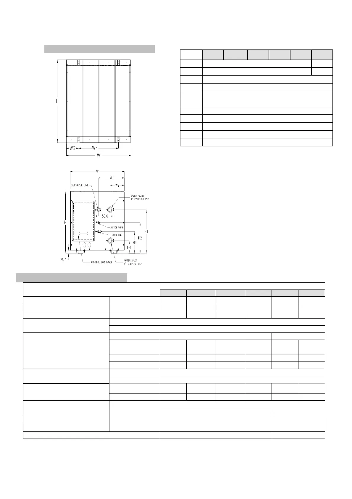
H
508.0 623.0
H1
355.0 549.0
H2
254.0
H3
179.0
H4
105.0
L
569.0
W
680.0
W1
329.0
W2
179.0
W3
130.0
W4
420.0
07KHP
MODEL
013 018 024 040 060 090
RATED CAPACITY (TONS) 1.0 1.5 2.0 3.0 5.0 7.5
CDU POWER INPUT (kW) 1.08 1.75 2.22 3.15 5.15 6.45
NET WEIGHT (kg) 52 54 63 70 78 93
Type R-22
REFRIGERANT
Charging method By Superheat Method
Type Rotary Scroll
Compr. Model RH189NRAT RH277NHDT PH39NPBT NH52NAHT ZR61KC-TF5 ZR81KC-TF5
RLA (A) 4.8 7.8 12.6 16.8 20.7 25.0
LRA (A) 35 47 66 91 139 179
COMPRESSORS
Refill Oil Charged (lit. / oz) 0.52 / 17.6 0.52 / 17.6 0.90 / 30 1.30 / 44 1.83 / 62 1.66 / 56
Quantity 1
PLATE HEAT EXCHANGER
(STAINLESS STEEL)
Water Inlet / Outlet ,mm (in.) 25.4 (1”) FPT
Suction,mm (in.) Flare Type 12.7 (1/2) 12.7 (1/2) 15.8 (5/8) 15.8 (5/8) 19.05 (3/4)
S-28.6
(1-1/8)
REFRIGERANT CONNECTIONS
Liquid, mm (in.) Flare Type 6.35 (¼) 6.35 (¼) 9.52 (3/8) 9.52 (3/8) 9.52 (3/8) S-15.8 (5/8)
High Press (PSIG) 426 ± 7 / 320 ± 20
CONTROL PRESSURESTAT SETTINGS
(Open / Close pressure settings)
Low Press (PSIG) n.a. 27 ± 4 / 67 ± 7
POWER SOURCE (V-Ph-Hz) NOMINAL (V) 208/230 - 1 - 60 230 - 3 - 60
PERMISSIBLE MIN-MAX VOLTAGE (V) 197 - 253
REFRIGERANT CONTROL DEVICE IN UNIT Capillary Tube Capillary*/Accurator**
RLA : Rated Load Amps LRA : Locked Rotor Amps
Data rated at 29.5° Water Out, 27°C/19°C Indoor Condition
* - Capillary tube located at FCU on model ASBFM0360-060 (Floor Standing)
** - Accurator is located at FCU on model 42AR0036-060 (Ceiling Type), 42GKX036-060(Cassette
type), 42LX036-060(Ceiling-Ducted). 7.5TR system normally uses TXV metering device.
Note
: Refill oil charge is for service use after compressor has been drained. This value is different
and less than Factory oil charged. Use only corresponding compressor maker approved specs.
(S) under refrigerant connections section means Sweat Type connection.
FIG. 2 DIMENSIONAL DRAWING
FRONT VIEW
TOP VIEW