2
INTRODUCTION
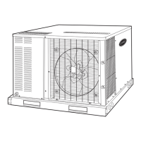
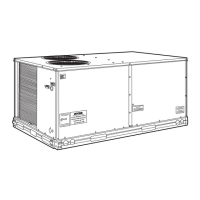
These instructions describe installation, start-up, and serv-
ice of 09DK020-044 air-cooled condensers (Fig. 1). See
Table 1 for general unit physical data.
INSTALLATION
Step 1 — Complete Pre-Installation Checks —
Examine for damage incurred during shipment. File claim
immediately with transit company if damage is found. Verify
that the nameplate electrical requirements match the available
power supply. Check the shipment for completeness.
Step 2 — Locate and Rig Unit, Remove Ship-
ping Skid
LOCATION — If roof installation is specified, make certain
that roof structure can support the condenser weight. Refer to
Table 1.
Locate condenser where an adequate supply of inlet outdoor
air is available. Do not locate where the possibility of air recir-
culation exists, such as under a roof overhang.
Locate condenser in an area free from airborne dirt or other
foreign material which could clog condenser coils.
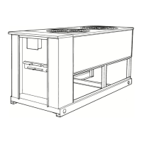
RIGGING — Preferred method is with spreader bars from
above the unit. Use 2-in. (50 mm) OD pipe or hooks in lifting
holes. Rig with 4 cables and spreader bars. All panels must be
in place when rigging. See rigging label on unit for details con-
cerning shipping weights, distance between lifting holes, cen-
ter of gravity, and spreader bar dimensions. Also see Fig. 2.
If overhead rigging is not possible, place unit on skid or pad
for rolling or dragging. When rolling, use minimum of 3 roll-
ers. When dragging, pull the pad. Do not apply force to the
unit. When in final position, raise from above to lift unit off
pad.
PLACING UNIT — There must be 4 ft (1.22 m) for service
and for unrestricted airflow on all sides of unit, and a minimum
of 8 ft (2.44 m) clean air space above units. See Fig. 3, 4, and
5. For multiple units, allow 8 ft (2.44 m) separation between
units for airflow and service.
MOUNTING UNIT — When unit is in proper location, use
mounting holes in base rails for securing unit to supporting
structure. Fasteners for mounting unit must be field supplied. If
unit is to be mounted on vibration isolators, drill mounting
holes in bottom of base rail at support points 1-4 (shown in
Fig. 3, 4, and 5) and locate isolators at those points.
Table 1 — Physical Data — 50 and 60 Hz
Fig. 1 — Model 09DK (Size 028 Shown)
All panels must be in place when rigging. Do not forklift
unit if no skid is supplied. If unit has skid, use forklift truck
from sides only.
Fig. 2 — Rigging with Spreader Bars
(Field Supplied)
UNIT
09DK
MAX. SHIP
WT
LIFTING
HOLES
CENTER OF
GRAVITY
D
ABC
lb kg in. mm in. mm in. mm in. mm
020,024 989 449 95.7 2432 55.2 1403 24.7 628 49.5 1256
028 1209 548 95.7 2432 54.7 1391 36.7 933 73.5 1867
034 1835 832 142.0 3608 80.0 2032 36.7 933 73.5 1867
044 2017 915 142.0 3608 80.0 2032 36.7 933 73.5 1867
UNIT 09DK 020 024 028 034 044
OPERATING WEIGHT, lb (kg)
Aluminum-Fin Units 797 (361.5) 797 (361.5) 983 (445.9) 1495 (678.1) 1676 (760.2)
Copper-Fin Units 921 (417.8) 921 (417.8) 1137 (515.7) 1700 (771.1) 1984 (900.0)
CONDENSER FANS, TYPE Propeller Type, Direct Driven
No. 22233
Diam, in. (mm) 30 (762)
Total Airflow cfm 10,600 13,500 15,700 21,100 23,700
L/s 5,000 6,370 7,400 9,950 11,200
Speed, Rpm (rps) 1140 (19), 60 Hz 950 (15.8), 50 Hz
CONDENSER COIL, TYPE Horizontal, Plate Fin
Rows 33223
Fins/in. (Fins/m) 17 (669) 17 (669) 19 (748) 17 (669) 17 (669)
Total Face Area, sq ft 23.5 23.5 39.2 58.4 58.4
sq m 2.18 2.18 3.64 5.43 5.43
 Loading...