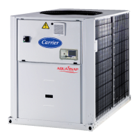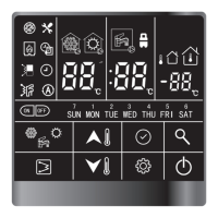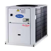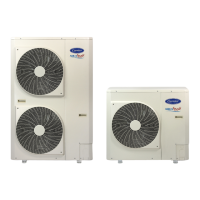
Do you have a question about the Carrier AquaSnap 61AF 055 and is the answer not in the manual?
| Model | 61AF 055 |
|---|---|
| Refrigerant | R-410A |
| Power Supply | 400V/3Ph/50Hz |
| Type | Air-Cooled Scroll Chiller Heat Pump |
| Operating Range (Cooling) | 10 to 46 °C |
Covers operating checks, refrigerant handling, protection device checks, and logbook requirements.
Guidelines for safe repair operations, including handling pressure, components, and tools.
Ensures safe installation practices, including access, protection, and handling of components.
Essential safety guidelines for performing maintenance on the unit.
Essential checks before system start-up, verifying installation against drawings and regulations.
Details compressor usage and electrical specifications for standard units.
Provides short-circuit stability current values for TN systems.
Specifies the operational temperature and pressure limits for the unit.
Guidance on power supply requirements and checking phase voltage imbalance.
General advice for water circuit design, fluid compatibility, and installation practices.
Measures and methods for protecting the unit from frost damage.
Procedure for controlling water flow using variable speed pump settings.
Procedure for controlling water flow using fixed speed settings and cleaning the circuit.
Essential checks to perform before attempting to start the heat pump.
Guidelines for commissioning and starting up the unit with a qualified engineer.
Information on R-407C refrigerant, leak detection, and charging procedures.
Details on the high-pressure safety switch and its monitoring during operation.
Specific electrical data for 61AF units equipped with Option 11.
Routine checks for users, including visual inspection and basic parameter verification.
Table of saturated pressure and temperature data for R-407C refrigerant.
Detailed maintenance involving electrical, hydraulic, and mechanical checks.
Advanced maintenance requiring manufacturer or authorized personnel expertise.
Checks related to unit start-up, including pump interlocks, oil level, and leak tests.
Steps for configuring user menu settings and initiating unit start-up.


