10.4 - Supplementary electric resistance
heaters
To permit staging of the capacity reduction of the heat pump at
low ambient temperatures, as shown in the diagram below, it is
possible to install supplementary electric heaters in the leaving
water line. Their capacity can compensate for the capacity drop
of the heat pump.
These heaters can be controlled via an integrated electronic board.
Four outputs are available to control the heater contactors,
permitting gradual compensation of the heat pump capacity
reduction.
These outputs are congurable to obtain a choice of two, three or
four stages. The last stage will only be activated after a shut-down
of the heat pump following a fault condition (safety device). This
requires only a 400 V-3 ph-50 Hz power supply source.
For the required conguration of the stages consult the 61AF
SmartVu
TM
control manual.
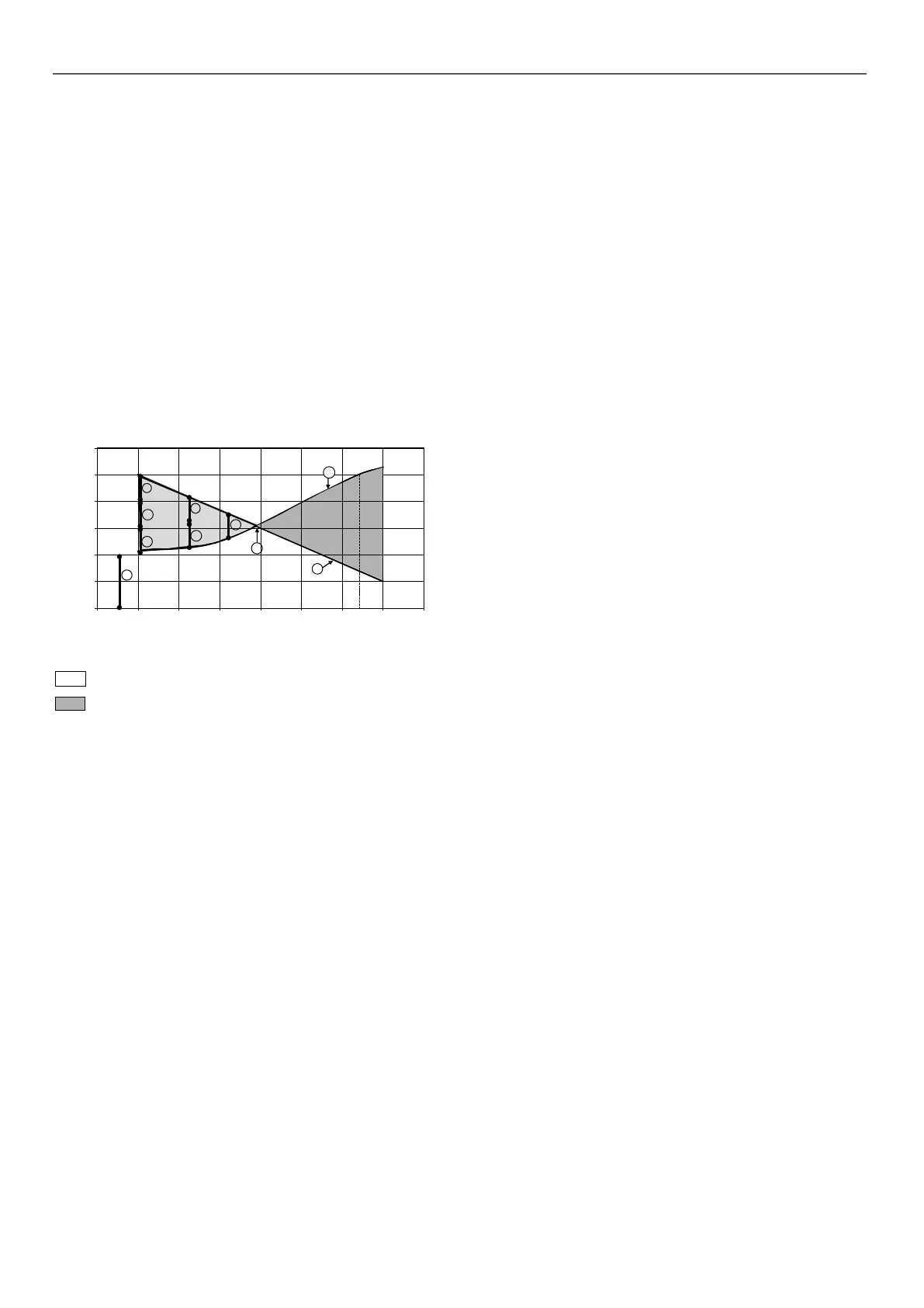
Example of additional electric heaters
0
20
40
60
80
100
120
-25-20 -15-10 -5 0510 15
4
1
2
3
1
2
1
C
B
A
Outdoor air temperature, °C
Pump capacity, %
1
Operating range, in which the heat pump capacity is lower than the building
thermal loadt
Operating range, in which the heat pump capacity is higher than the building
thermal load
Legend
1 Stage 1 2 Stage 2 3 Stage 3 4 Stage 4
A Heat pump capacity variation as a function of the air temperature
B Building thermal load
C Balance point between the capacity supplied by the heat pump and the thermal
load of the building
10 - START-UP
 Loading...


