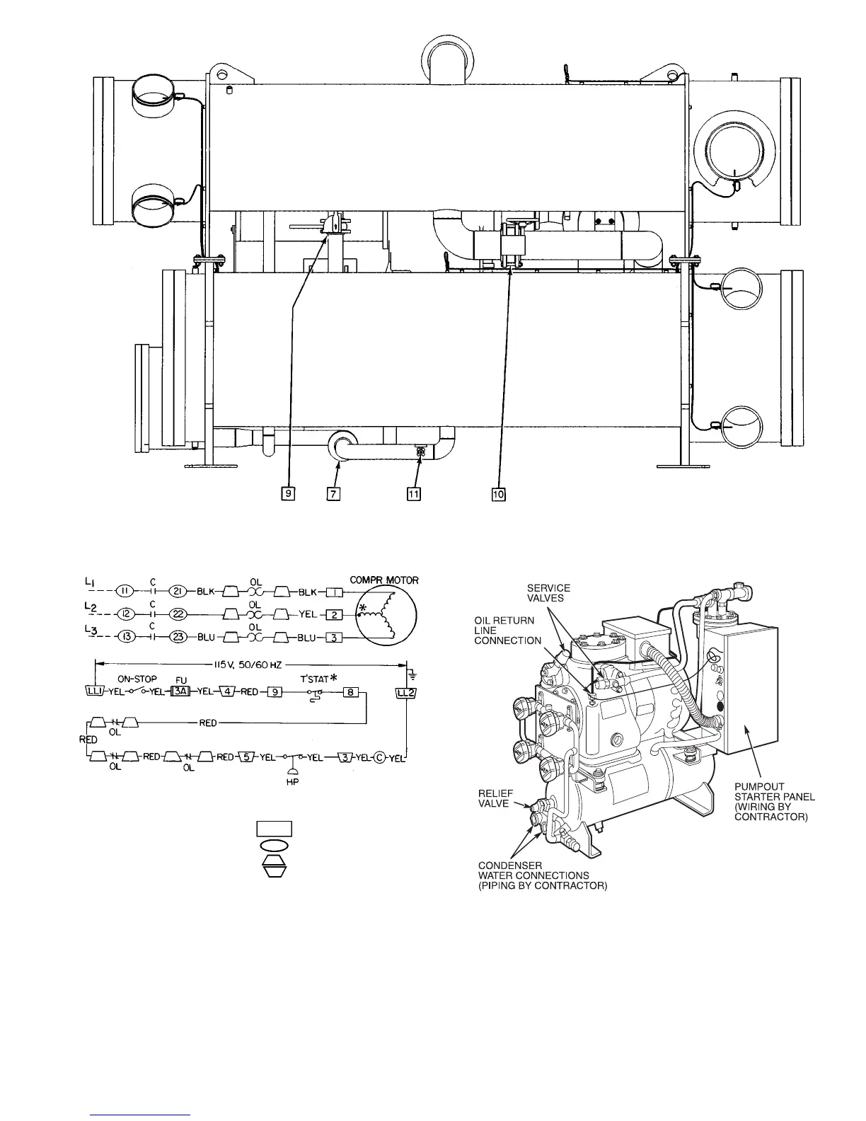
Fig. 32 — Pumpout Arrangement and Valve Number Locations (12-ft Vessel Shown) (cont)
LEGEND
C—Contactor
Fu — Fuse, 3 Amps
HP — High-Pressure Cutout
OL — Compressor Overload
T’stat — Internal Thermostat
Compressor Terminal
Contactor Terminal
Overload Terminal
Pumpout Unit Terminal
*Bimetal thermal protector imbedded in motor winding.
Fig. 33 — Pumpout Unit Wiring Schematic
(19EX Shown)
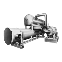
Fig. 34 — Optional Pumpout Compressor
65