This document is an installation manual for a Carrier ceiling and floor air conditioner. It provides comprehensive instructions for installing, connecting, and testing the unit, ensuring proper operation and safety.
Function Description:
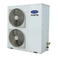
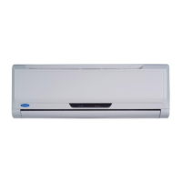
The Carrier air conditioning system is designed to provide cooling for indoor spaces. It consists of an indoor unit and an outdoor unit, which are connected by refrigerant piping and electrical wiring. The system operates by circulating refrigerant to absorb heat from the indoor air and release it outdoors, thereby lowering the indoor temperature. The manual emphasizes the importance of correct installation to prevent issues such as water leakage, electrical shock, fire, or equipment failure.
Important Technical Specifications:
General:
- Installation Standards: Must comply with local and national standards.
- Power Voltage: Should be within 90-110% of the rated voltage.
- Circuit Breaker/Fuse: For auxiliary electric heating, an additional 10A is required.
- Cable Type: H07RN-F cables are recommended for power and signal connections. In North America, cable types should adhere to local electrical codes.
Indoor Unit:
- Installation Clearance: Minimum 35mm clearance on sides and top, and 1000mm from the bottom.
- Drain Tilt: Minimum drain tilt of 1/100 or more to ensure proper water drainage.
- Connecting Pipe Assembly (Liquid Side): Available in diameters of ø6.35 (1/4 in), ø9.52 (3/8in), and ø12.7 (1/2in).
- Connecting Pipe Assembly (Gas Side): Available in diameters of ø9.52 (3/8in), ø12.7 (1/2in), ø16 (5/8in), ø19 (3/4in), and ø22 (7/8in).
- Power Supply Specifications (Indoor):
- 1 Phase (208-240V):
- ≤18K BTU/h: 25/20A
- 19K-24K BTU/h: 32/25A
- 25K-36K BTU/h: 50/40A
- 37K-48K BTU/h: 70/55A
- 49K-60K BTU/h: 70/60A
- 3 Phase (380-420V):
- ≤36K BTU/h: 25/20A
- 37K-60K BTU/h: 32/25A
- 3 Phase (208-240V):
- ≤36K BTU/h: 32/25A
- 37K-60K BTU/h: 45/35A
Outdoor Unit:
- Installation Clearance: Minimum 60cm (24in) above, 30cm (12in) left, 30cm (12in) from back wall, 200cm (79in) front, and 60cm (24in) right.
- Refrigerant Piping (Maximum Length and Drop Height):
- North America, Australia, EU Frequency Conversion Split Type:
- <15K BTU/h: 25/82m length, 10/32.8m drop height
- ≥15K - <24K BTU/h: 30/98.4m length, 20/65.6m drop height
- ≥24K - <36K BTU/h: 50/164m length, 25/82m drop height
- ≥36K - ≤60K BTU/h: 65/213m length, 30/98.4m drop height
- Other Split Type:
- 12K BTU/h: 15/49m length, 8/26m drop height
- 18K-24K BTU/h: 25/82m length, 15/49m drop height
- 30K-36K BTU/h: 30/98.4m length, 20/65.6m drop height
- 42K-60K BTU/h: 50/164m length, 30/98.4m drop height
- Oil Traps: Recommended every 6m (20ft) for units <36000BTU/h and every 10m (32.8ft) for units ≥36000BTU/h in vertical suction lines.
- Power Supply Specifications (Outdoor):
- 1 Phase (208-240V):
- ≤18K BTU/h: 25/20A
- 19K-24K BTU/h: 32/25A
- 25K-36K BTU/h: 50/40A
- 37K-48K BTU/h: 70/55A
- 49K-60K BTU/h: 70/60A
- 3 Phase (380-420V):
- ≤36K BTU/h: 25/20A
- 37K-60K BTU/h: 32/25A
- 3 Phase (208-240V):
- ≤36K BTU/h: 32/25A
- 37K-60K BTU/h: 45/35A
Refrigerant Charging:
- R22 (Indoor Unit Orifice Tube): (Total pipe length - standard pipe length) x 30g (0.32oz)/m(ft) for ø6.35, x 65g (0.69oz)/m(ft) for ø9.52, x 115g (1.23oz)/m(ft) for ø12.7.
- R22 (Outdoor Unit Orifice Tube): (Total pipe length - standard pipe length) x 15g (0.16oz)/m(ft) for ø6.35, x 30g (0.32oz)/m(ft) for ø9.52, x 60g (0.64oz)/m(ft) for ø12.7.
- R410A (Indoor Unit Orifice Tube): (Total pipe length - standard pipe length) x 30g (0.32oz)/m(ft) for ø6.35, x 65g (0.69oz)/m(ft) for ø9.52, x 115g (1.23oz)/m(ft) for ø12.7.
- R410A (Outdoor Unit Orifice Tube): (Total pipe length - standard pipe length) x 15g (0.16oz)/m(ft) for ø6.35, x 30g (0.32oz)/m(ft) for ø9.52, x 65g (0.69oz)/m(ft) for ø12.7.
- R32: (Total pipe length - standard pipe length) x 12g (0.13oz)/m(ft) for ø6.35, x 24g (0.26oz)/m(ft) for ø9.52, x 40g (0.42oz)/m(ft) for ø12.7.
- Warning: Do not mix refrigerant types.
Usage Features:
- Remote Control: The system includes a remote control for convenient operation.
- Display Panel: The indoor unit features a display panel for status indication.
- Manual Buttons: Manual control options are available on the indoor unit.
- Airflow Louver: Adjustable louvers at the air outlet to direct airflow.
- Air Filter: The air inlet includes an air filter for improved air quality.
Maintenance Features:
- Installation and Maintenance Space: Adequate room is required around the unit for easy installation and future maintenance.
- Refrigerant Leak Check: Instructions are provided for checking refrigerant leaks after installation.
- Air Evacuation: Detailed steps for evacuating air and non-condensable gases from the refrigerant circuit using a vacuum pump and manifold gauge.
- Drainage Test: Procedures for testing the drainage system to ensure smooth and unimpeded water flow.
- Wiring Diagram: Electrical connection diagrams are provided inside the electrical box cover for reference during wiring.
- Troubleshooting: The manual refers to a troubleshooting section in the Owner's Manual for resolving operational issues.