14
e. When chiller pressure rises to 40 psig (276 kPa),
turn on the pumpout compressor until the pressure
again reaches 35 psig (241 kPa), then, turn off the
pumpout compressor. Repeat this process until the
chiller pressure no longer rises; then, turn on the
pumpout compressor and pump out until the chiller
pressure reaches 18 in. Hg vacuum (41 kPa abso-
lute). This can be done in On or Automatic mode.
f. Close valves 1a, 1b, 3, 4, and 6.
g. Turn off the pumpout condenser water.
4. Establish vacuum for service. To conserve refrigerant,
operate the pumpout compressor as described in Step 3e
until the chiller pressure is reduced to 18 in. Hg
vacuum (41 kPa absolute).
This operation can be done in Automatic or On mode.
In Automatic mode, the compressor will stop automati-
cally at approximately 15 in. Hg vacuum (51 kPa
absolute).
CHILLERS WITH ISOLATION VALVES — The valves
referred to in the following instructions are shown in Fig. 9 and
11. Valve 7 remains closed.
Transfer All Refrigerant to Chiller Condenser Vessel
1. Push refrigerant into chiller condenser vessel.
a. Turn on the chiller water pumps and monitor the
chiller pressure.
b. Valve positions:
c. Equalize the refrigerant in the chiller cooler and
condenser.
d. Turn off chiller water pumps and pumpout con-
denser water supply.
e. Turn on pumpout compressor to push liquid out of
the chiller cooler vessel.
f. When all liquid has been pushed into the chiller
condenser vessel, close the cooler refrigerant isola-
tion valve (11).
g. Turn on the chiller water pumps.
h. Turn off the pumpout compressor.
2. Evacuate gas from chiller cooler vessel.
a. Close pumpout valves 2 and 5; open valves 3
and 4.
b. Turn on pumpout condenser water.
c. Run pumpout compressor until the chiller cooler
vessel pressure reaches 18 in. Hg vacuum (41 kPa
absolute). Monitor pressures on the chiller control
panel and on refrigerant gages.
This operation can be done in Automatic or On
mode. In Automatic mode, the compressor will
stop automatically at approximately 15 in. Hg
vacuum (51 kPa absolute).
d. Close valve 1a.
e. Turn off pumpout compressor.
f. Close valves 1b, 3, and 4.
VALVE 1a1b2345671011
CONDITION CCCCCCCCC
VALVE 1a1b234511
CONDITION C C
VALVE 1a 1b 2 3 4 5 11
CONDITION C C C
VALVE 1a 1b 2 3 4 5 11
CONDITION CCCCCCC
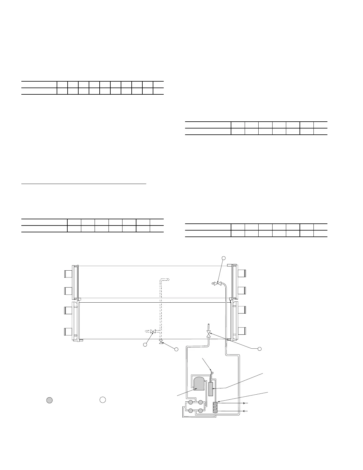
OIL
SEPARATOR
PUMPOUT
CONDENSER
WATER SUPPLY
AND RETURN
PUMPOUT
CONDENSER
2
3
4
5
PRESSURE
RELIEF SAFETY
VALVE
PUMPOUT
COMPRESSOR
SERVICE VALVE
SERVICE VALVE
COOLER
REFRIGERANT
ISOLATION
VALVE
REFRIGERANT
CHARGING
VALVE
CHILLER
CONDENSER
VESSEL
CHILLER
COOLER
VESSEL
7
11
1a
1b
SERVICE VALVE ON
PUMPOUT UNIT
=
SERVICE VALVE ON
CHILLER
=
Fig. 11 — Valve Locations for 19XR Pumpout Unit Without Storage Tank
 Loading...


