4
SPECIFICATIONS
Table 3—Specifications
COOLING ONLY HEAT PUMP
System
Size 18 22 28 32 32 32 24 28
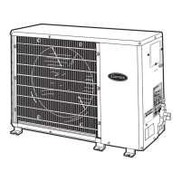
Outdoor Model
24AH A 418A 003
124AN S018000
24AH A 424A 003
124AN S024000
24AH A 430A 003
124AN S030000
24AH A 436A 003
124AN S036000
24AH A 436A 005
124APS 036000
24AH A 436A 006
124AE S 036000
25HH A 424A 003
224AN S024000
25HH A 430A 003
224AN S030000
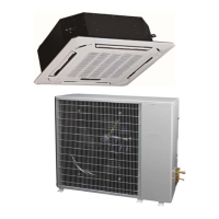
Indoor Model 40MK CB 18B----3 40MK CB 22B----3 40MK CB 28B----3 40MK CB 32B----3 40MK C B32B----3 40MK CB 32B----3 40MKQ B24B----3 40MK Q B 28B----3
Performance
Cooling Rated Capacity Btu/h 18,000 21,600 28,000 32,000 32,000 32,000 22,800 27,600
SEER 14.0 14.0 14.0 14.0 14.0 14.0 14.0 14.0
EER 12.2 12.2 12.2 12.2 12.2 12.2 12.0 12.2
Heating Rated Capacity Btu/h N/A 22,000 27,800
HSPF N/A 8.2 8.2
COP W/W N/A 3.86 3.72
Controls
Wire less Remote Controller (° F/° C
Convertibl e )
Sta ndard Sta ndard Sta ndard Sta ndard Sta ndard Sta ndard S t a ndard Sta ndard
Operating
Range
W i r ed Remot e Controll e r (° F/° C
Convertibl e )
Opti onal Opti onal N/A N/A N/A N/A N/A N/A
Cooli ng Outdoor D B Min --
Max
° F 55~125 (--20° F w / Low--Ambi ent Kit) 55~125 (--20° F w / Low--Ambi ent Kit)
He a t i ng Outdoor D B Mi n --
Max
° F
N/A 17~75 17~75
Cooli ng Indoor DB Min
-- M a x
° F
64~90 64~90 64~90 64~90 64~90 64~90 64~90 64~90
He a t i ng Indoor DB Min
-- M a x
° F
N/A 32~80 32~81
Piping
Total Piping Length** Ft. 200’ 200’ 200’ 200’ 200’ 200’ 200’ 200’
Dr op (O D above ID) Ft. 200’ 200’ 200’ 200’ 200’ 200’ 200’ 200’
Lift (OD below ID) Ft. 65’ 65’ 65’ 65’ 65’ 65’ 65’ 65’
Outdoor Pipe Connect i on
Siz e -- Liquid*
In. 3/8” 3/8” 3/ 8” 3/8” 3/ 8” 3/8” 3/8” 3/8”
Outdoor Pipe Connect i on
Size -- Suction
In. 5/8” 3/4” 3/ 4” 7/8” 7/ 8” 7/8” 3/4” 3/4”
Indoor Pipe Connect i on Siz e
-- Liqui d
In. 3/8” 3/8” 3/ 8” 3/8” 3/ 8” 3/8” 3/8” 3/8”
Indoor Pipe Connect i on Siz e
-- Suction
In. 5/8” 3/4” 3/ 4” 7/8” 7/ 8” 7/8” 3/4” 3/4”
Refrigerant
Type R--410A R--410A R--410A R--410A R--410A R--410A R--410A R--410A
Design Pressure PSIG 550 550 550 550 550 550 550 550
Me t e ring Devi c e Type B Ac c urator Type B Ac c urator
Charge Lb. 6.4 6.5 8.6 8.9 8.9 8.9 7.7 12.1
Ou tdoor
Coil
Face Area Sq. Ft. 7.3 7.3 12.1 12.1 12.1 12.1 7.3 12.1
No. Rows 2 2 2 2 2 2 2 2
Fins per inch 20 20 20 20 20 20 20 20
Circuits 3 3 3 3 3 3 3 6
Indoor
Coil
Face Area (sq. ft.) Sq. Ft. 3.9 3.9 4.7 4.7 4.7 4.7 4. 7 4.7
No. Rows 2 2 3 3 3 3 3 3
Fins per inch 21 21 18 18 18 18 18 18
Circuits 6 6 9 9 9 9 9 9
Compressor
Type Scroll Scroll Scroll Scroll Scroll Scroll Sc roll Scroll
Mode l
ZP 16K 6E--PFV--13
0
ZP 20K 6E--PFV--13
0
ZP 25K 5E--PFV--13
0
ZP 29K 5E--PFV--13
0
ZP 29K 5E--TF5--13
0
ZP 29K 5E--TFD--130 ZP21K5E--PFV--13
0
ZP 24K 5E--PFV--13
0
Electrical
Outdoor Volta ge , P ha se,
Cycle
V/Ph/Hz 208/230--1--60 208/230--1--60 208/230--1--60 208/230--1--60 208/230--3--60 460--3--60 208/230--1--60 208/230--1--60
Indoor Volta ge , Pha s e , Cycle V/Ph/Hz 208/230--1--60 208/230--1--60 208/230--1--60 208/230--1--60 208/230--1--60 208/230--1--60 208/230--1--60 208/ 230--1--60
Power Supply Indoor and outdoor units have dedic ated power suppl y
Indoor and outdoor units have dedica t e d
powe r supply
MCA ( O ut door) A. 11.8 14.1 18.3 18.3 12.5 7.6 16. 5 17.2
MOCP -- Fuse Rating
(O ut door)
A. 20 25 30 30 20 15 25 30
MCA ( Indoor) A. 1 1 1 1 1 1 1 1
MOCP -- Fuse Rating
(Indoor)
A. 15 15 15 15 15 15 15 15
Ou tdoor
Unit Width In. 36.9 36.9 44.5 44.5 44.5 44.5 36.9 44.5
Unit Height In. 31.1 31.1 37.1 37.1 37.1 37.1 31.1 .1
Unit Depth In. 14.6 14.6 17.1 17.1 17.1 17.1 14.6 .1
Ne t Weight Lbs. 146. 0 148.0 183.0 184.0 184.0 .0 161.0 196.0
Airflow CFM 1285 1285 1900 2615 2615 2615 1285 2615
Indoor
Unit Width In. 46.7 46.7 57.1 57.1 57.1 .1 57.1 57.1
Unit Height In. 13.4 13.4 13.4 13.4 13.4 .4 13.4 13.4
Unit Depth In. 10.2 10.2 10.4 10.4 10.4 .4 10.4 10.4
Ne t Weight Lbs. 37.5 37.5 55.1 55.1 55.1 .1 55.1 55.1
Number of Fan Speeds 4 4 4 4 4 4 4 4
Airf l ow (l owest to highes t) CFM 475/570/695/ 710 475/570/ 695/ 710 525/685/ 834/ 847 525/685/834/ 847 525/685/ 834/ 847 525/685/834/ 847 525/685/834/ 847 525/685/ 834/ 847
Sound Pre ss ure (lowest to
highes t )
dB(A) 44/47/50/ 51 44/47/50/51 46/48/52/53 46/48/52/53 46/48/52/53 46/48/ 52/ 53 46/48/52/ 53 46/48/52/53
Air throw Da t a Ft. 20 20 25 25 25 25 25 25
* Liquid line needs to be insulated
** Refer to Ductless Split System Long Line Guide for additional information. Long Line accessories required beyond 80 ft (24.4 m).
Legend
SEER ---- -- Seasonal Energy Efficiency Ratio
EER ------ Energy Efficiency Ratio
MCA -- -- -- M i n i m u m C i r c u i t A m p s
MOCP -- -- -- M a x . O v e r -- -- -- C u r r e n t P r o t e c t i o n
 Loading...