6
Install Liquid Line Filter Drier
Indoor
CAUTION
!
UNIT DAMAGE HAZARD
Failure to follow this caution may result in equipment damage
or improper operation.
Installation of filter drier in liquid line is required.
CAUTION
!
UNIT DAMAGE HAZARD
Failure to follow this caution may result in equipment
damage or improper operation.
Filter drier must be wrapped in a heat---sinking material
such as a wet cloth while brazing.
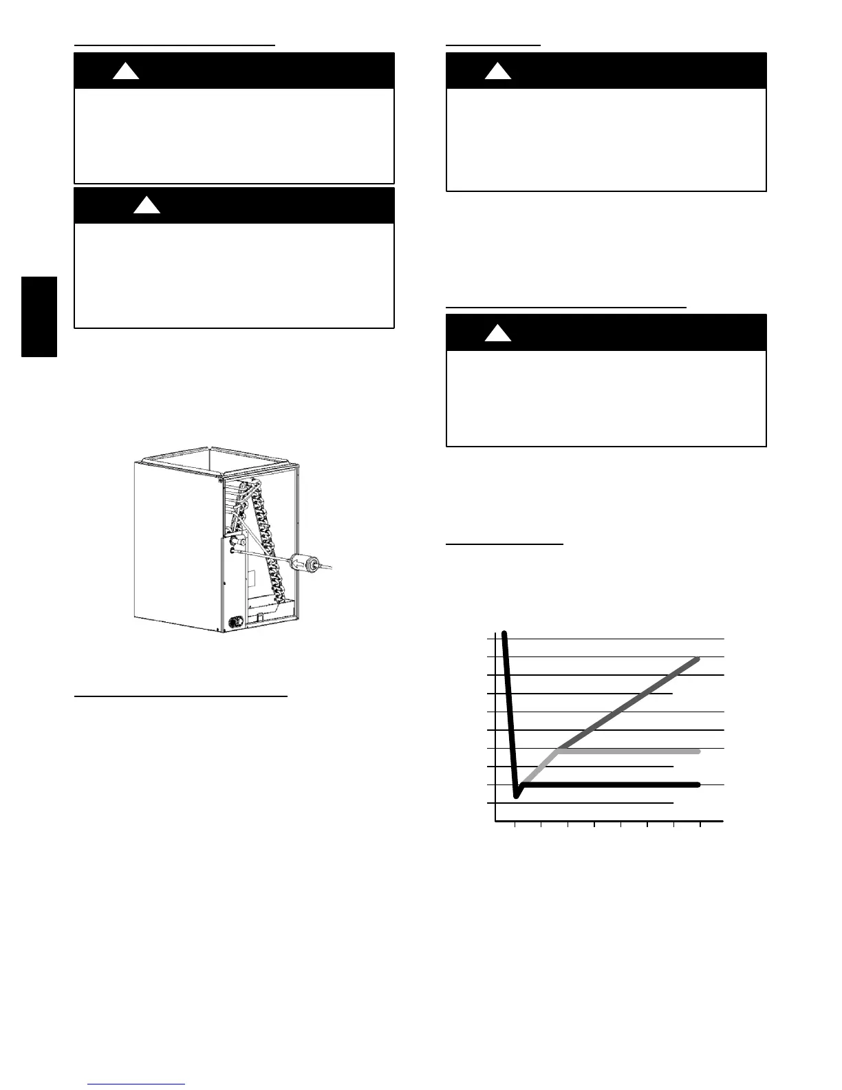
Refer to Fig. 5 and install filter drier as follows:
1. Braze 5-- in. liquid tube to the indoor coil.
2. Wrap filter drier with damp cloth.
3. Braze filter drier to above 5” liquid tube. Flow arrow
must point towards indoor coil.
4. Connect and braze liquid refrigerant tube to the filter drier.
A05178
Fig. 5 --- Liquid Line Filter Drier
Refrigerant Tubing Connection
Outdoor
Co n n ect v ap o r tu b e to fitting on o utdoor unit vapor service
valv es (see Table 1.) Co n n ect an d b raze th e 3/8 ” co u plin g
(provided with the filter drier) to the liquid service valve and
con nect an d braze th e liquid tub in g to th e o th er en d of this
coupling. Use refrigerant grade tubing.
Sweat
Connection
CAUTION
!
UNIT DAMAGE HAZARD
Failure to follow this caution may result in equipment
damage or improper operation.
Service valves must be wrapped in a heat-- sinking
material such as a wet cloth.
Service valves are closed from factory and ready for brazing.
After wrapping service valve with a wet cloth, braze sweat
connections using industry accepted methods and materials.
Consult local code requirements. Refrigerant tubing and indoor
coil are now ready for leak testing. This check should include all
field and factory joints.
Evacuate Refrigerant Tubing and Indoor
Coil
CAUTION
!
UNIT DAMAGE HAZARD
Failure to follow this caution may result in equipment
damage or improper operation.
Never use the system compressor as a vacuum pump.
Refrigerant tubes and indoor coil should b e evacuated using the
recommended deep vacuum method of 500 microns. An alternate
triple ev acuatio n meth od may b e used if th e deep v acuu m
procedure is not followed.
IMPORTANT: Always break a vacuum with dry nitrogen.
Deep Vacuum
Method
The deep vacuum method requires a vacuum pump capable of
pulling a vacuum of 500 microns and a vacuum gage capable of
accurately m easurin g this vacu um depth . The d eep vacu um
method is the most positive way of assuring a system is free of air
and liquid water. (See Fig. 6)
500
MINUTES
01234567
1000
1500
LEAK IN
SYSTEM
VACUUM TIGH
TOO WET
TIGHT
DRY SYSTEM
2000
2500
3000
3500
4000
4500
5000
A95424
A95424
Fig. 6 --- Deep Vacuum Graph
24APA24APA
 Loading...