5
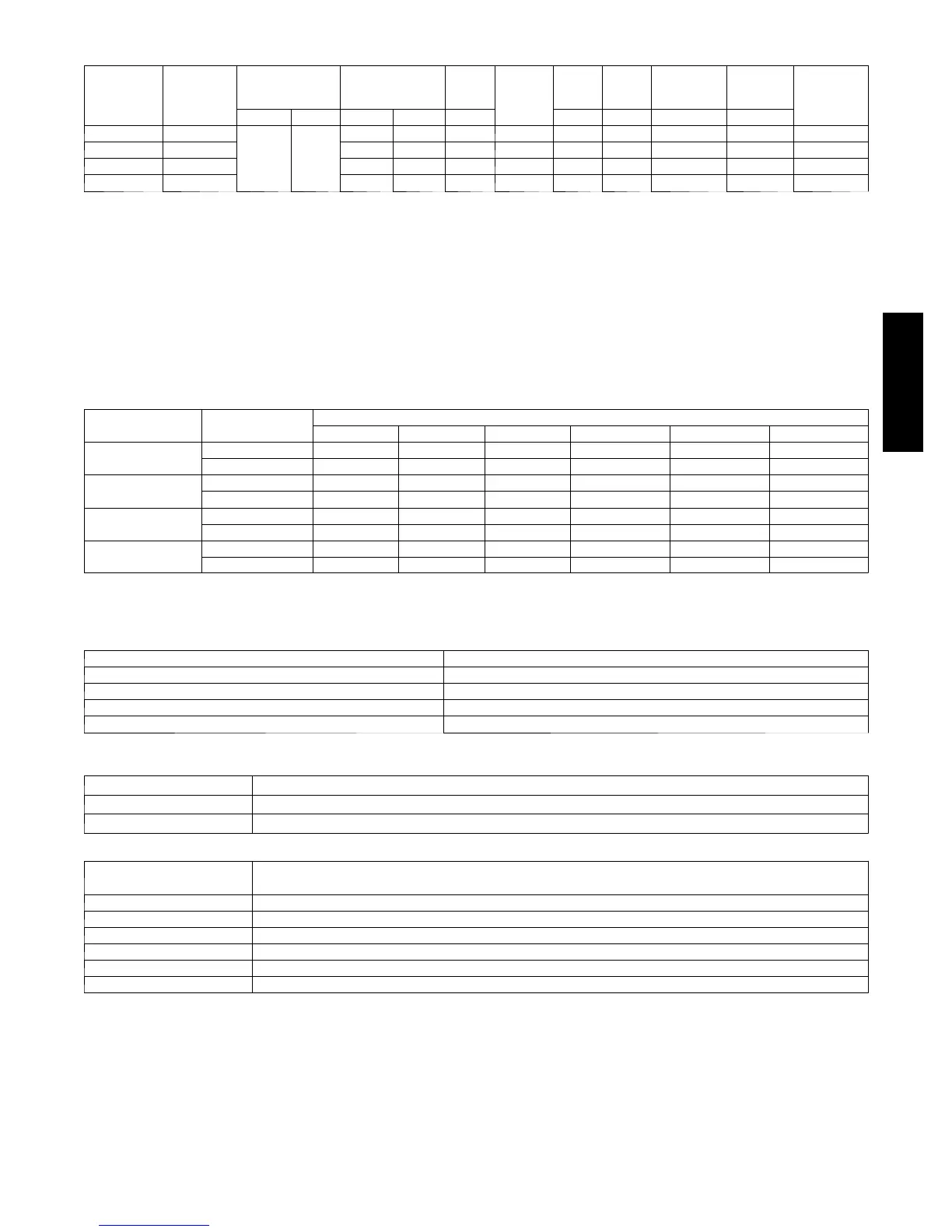
ELECTRICAL DATA
U n i t S i z e ---
Voltage,
Series
V/PH
OPER VOLTS* COMPR FAN
MCA
MIN
WIRE
SIZE{
MIN
WIRE
SIZE{
MAX
LENGTH
ft. (m)}
MAX
LENGTH
ft. (m)}
MAX
FUSE** or
CKT BRK
AMPS
MIN MAX RLA LRA FLA 60° C 75° C 60° C 75° C
24--- 30 208/230
187 253
10.30 52.0 0.7 13.58 14.00 14.00 60 (18.3) 57 (17.4) 20
36--- 30 208/230 16.70 82.0 1.2 22.08 12.00 12.00 57 (17.4) 54 (16.5) 35
48--- 31 208/230 21.20 96.0 1.3 27.80 10.00 10.00 72 (21.9) 68 (20.7) 40
60--- 31 208/230 23.00 118.0 1.3 30.06 8.00 10.00 93 (28.3) 57 (17.4) 50
* Permissible limits of the voltage range at which the unit will operate satisfactorily
{ If wire is applied at ambient greater than 30_C, consult table 310 ---16 of the NEC (NFPA 70). The ampacity of non---metallic---sheathed cable (NM), trade
name ROMEX, shall be that of 60_C conditions, per the NEC (NFPA 70) Article 336---26. If other than uncoated (no---plated), 60 or 75_C insulation, copper
wire (solid wire for 10 AWG or smaller, stranded wire for larger than 10 AWG) is used, consult applicable tables of the NEC (NFPA 70).
} Length shown is as measured one way along wire path between unit and service panel for voltage drop not to exceed 2%.
* * T i m e --- D e l a y f u s e .
FLA --- Fu l l L o a d A m p s
LRA --- L o c k e d R o t o r A m p s
MCA --- Minimum Circuit Amps
RLA ---RatedLoadAmps
NOTE: Control circuit is 24---V on all units and requires external power source. Copper wire must be used from service disconnect to unit.
All motors/compressors contain internal overload protection.
Complies with 2007 requirements of ASHRAE Standards 90.1
A--WEIGHTED SOUND POWER (dBA)
U n i t S i z e ---
Voltage, Series
Standard Rating
(dBA)
TYPICAL OCTAVE BAND SPECTRUM (dBA, without tone adjustment)
125 250 500 1000 4000 8000
24 --- 30
7 1 --- l o w st a g e 49.4 61.4 60.8 61.5 55.5 46.9
7 2 --- h i g h s t a g e 49.9 58.4 61.8 60.0 56.0 50.4
36 --- 30
7 2 --- l o w st a g e 48.9 57.9 64.3 62.0 55.5 50.9
7 4 --- h i g h s t a g e 49.4 59.4 62.3 64.0 56.5 52.4
48 --- 31
7 4 --- l o w st a g e 53.9 63.9 61.8 64.0 56.0 47.9
7 4 --- h i g h s t a g e 52.9 60.9 61.8 64.0 60.0 48.9
60 --- 31
7 3 --- l o w st a g e 51.9 58.9 65.3 61.5 55.0 48.4
7 3 --- h i g h s t a g e 52.4 61.4 62.3 64.0 56.0 49.9
NOTE: Tested in accordance with AHRI Standard 270---08. (Not listed with AHRI).
CHARGING SUBCOOLING (TXV--TYPE EXPANSION DEVICE)
UNIT SIZE--- VOLTAGE, SERIES REQUIRED SUBCOOLING _F(_C)
24--- 30 10 (5.6)
36--- 30 10 (5.6)
48--- 31 10 (5.6)
60--- 31 10 (5.6)
CONTROLS / THERMOSTATS
Infinity Controls DESCRIPTION
SYSTXCCUIZ01 ---B Infinity System Zone Control User Interface
SYSTXCCUID01 ---B Infinity System Non---Zone Control User Interface
THERMOSTAT / SU BBASE
PKG.
DESCRIPTION
T P --- P R H 0 1 --- A Programmable Thermidistat
T P --- N R H 0 1 --- A Non--- programmable Thermidistat
T P --- P H P 0 1 * Performance Series Programmable HP Stat
T P --- N H P 0 1 * Performance Series Non--- programmable HP Stat
T C --- P H P 0 1 * Comfort Series Programmable HP Stat
T C --- N H P 0 1 * Comfort Series Non --- programmable HP Stat
*Serial numbers beginning with 2909 and thereafter.
24APA7

 Loading...