10
Step 11 — System Functions and Sequence of
Operation
The 24VNA9 mod els utilize either Infinity Touch Communicating
User Interface (UI) or conventional thermostat. When using UI
controls, a call for cooling will energize the outdoor fan and
compressor to run at lowest cooling demand. If this does not satisfy
cooling demand, the system will ramp up in stages until it satisfies
the demand. After coping with the higher demand, the unit returns
to lower capacity operation until the demand is satisfied or until an
increase in demand. When using a conventional thermostat, the
thermostat controls the staging of outdoor unit.
Upon initial start--up of unit, status code 68 will be generated and
system will operate at stage 2 for 11 minutes. This operation is
important to system reliability and cannot be bypassed. Each time
high voltage is removed and reapplied this behavior will be
repeated.
When all demand is satisfied, the compressor will shut off. As the
unit operates at lower capacity, system vapor (suction) pressure will
be higher than it is during a standard single--stage system operation
or during a higher capacity operation.
The user interface (UI) displays the operation mode and fault codes
as specified in the troubleshooting section. See Table 6 for codes
and definitions.
The conventional thermostat inputs are designed to work with most
indoor units. See AHRI for approved combinations. Connections
are Y/Y2, Y1, R and C. Depending on thermostat and indoor unit,
the system will operate at 1 or 2 capacities in cooling mode.
NOTE: Only one code will be displayed on the outdoor unit
control board (the most recent, with the highest priority). The
latest codes are stored and can be accessed via the UI.
Upon a call for cooling through the UI (or the Y1 and/or Y2
connections in a non-- communicating system), the Application
Operation Control (AOC) board (see Fig. 27) will request a
compressor speed and outdoor fan motor speed based on the
indoor space demand and outdoor conditions.
If the conditions are correct for operation, the control board will
allow the requested operation to begin, but if the control board
determines that the conditions are not correct, the board will decide
what other operation nearing that condition is acceptable. The
inverter Motor Operational Control (MOC) then outputs the
three--phase PWM signal and frequency that gently ramps the
compressor speed up to stage 2, and then will adjust to the
demanded speed. The gentle ramp-- up results in no locked rotor
amps to the compressor motor. The unit nameplate for compressor
LRA will be stamped N/A (not applicable).
During operation, the AOC monitors itself and the compressor
operation along with the system pressures and temperatures. The
MOC board monitors the temperature, current and operational
status of the compressor, OD fan and the inverter itself. During
operation, the compressor speed will be adjusted to meet the
changes to the demand.
Step 12 — Check Charge
Charge in CHARGING mode (communicating only)
Unit is factory charged for 15ft (4.57 m) of lineset. If any
refrigerant charge adjustment is required due to the user inputted
line set length, the UI will calculate and display the target
subcooling and the amount of additional charge to be added.
Therefore, the UI is your source of information for charging the
system correctly. Refrigerant charge adjustment amount for adding
or removing 0.6 oz/ft (17.74 g/m) of 3/8 liquid line above or below
15ft (4.57 m) respectively. Perform a final charge check only when
in cooling and OD is between 65_F(18_C) and 100_F(38_C).
The use of a commercial charge metering device (restrictor) such as
Imperial liquid low side charger model 535--C or Watsco
ChargeFaster model CH200 is recommended when adding
refrigerant to an operating system. This prevents potential damage
of liquid slugging of the compressor and allows the subcooling to
stabilize quicker.
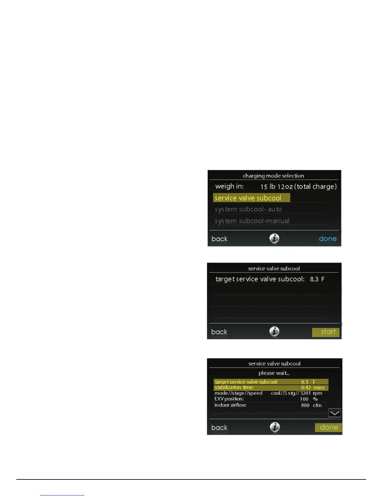
Charging using the subcooling method optimizes charge volume
and is preferred if possible. If the outdoor temperature is between
65_F -- 100_F (18.3_C -- 37.8_C) and indoor temperature is 70_F
-- 8 0 _F (21.1_C -- 26.7_C), the option to further adjust charge
using “service valve subcool” will be available in the “charging
mode selection” screen. If temperatures are outside of range, this
option will be greyed out and not selectable.
Initial start--up can be performed using calculated charge only and
once conditions are within range, the ”Service Valve Subcool”
option will become selectable.
Once start is selected the system will operate in a preset mode until
“done” is selected. Wait for required stabilization time then check
subcooling at service valve.
Adjust charge as required to meet target service valve subcooling
shown on screen +/--1 degree. If any adjustment is necessary, add
or remove the charge slowly (no greater than .5 lb per minute) and
allow system to operate for 25 minutes to stabilize, before
declaring a properly charged system.
A14573
Fig. 16 -- Adjusting Charge Using Service Valve Subcool
A14574
Fig. 17 -- Service Valve Subcool Target Value
A14575
Fig. 18 -- Stabilization Time
Manufacturer reserves the right to change, at any time, specifications and designs without notice and without obligations.
Catalog No: 24
N
9 --- 3 S I ( r e v 1 )
Replaces: 24VNA9---2SI
 Loading...