Do you have a question about the Carrier 25TPA7 and is the answer not in the manual?
Key safety warnings and precautions for installation, including DANGER, WARNING, and CAUTION.
Warning regarding potential electrical shock hazard during installation and service.
Warning regarding explosion hazard related to refrigerant handling and compressors.
Guidelines and best practices for unit placement and piping installation.
Caution about sharp edges on sheet metal parts and need for protective gear.
Steps to inspect the unit and prepare the installation site according to standards.
Instructions for mounting the unit on a level pad and maintaining necessary clearances.
Guidance on checking the defrost thermostat and elevating the unit for drainage and snow clearance.
Instructions for making refrigerant piping connections, emphasizing safety.
Warnings about refrigerant handling, pressure relief, and venting regulations.
Caution regarding potential equipment damage from improper piping or burial.
Instructions on handling and preparing service valves, including piston installation.
Warnings about fire hazards during brazing and the need for heat sinking and protective gear.
Procedure for installing the liquid line filter drier, including brazing precautions.
Procedure for evacuating the system using the deep vacuum method, avoiding compressor use.
Warning about electrical shock hazard and proper grounding of the unit.
Instructions for connecting ground, power wiring, and control wiring to the unit.
Illustrations showing thermidistat wiring for fan coil and furnace configurations.
Final verification of wiring and tubing security before closing panels.
Information on the crankcase heater and its power requirements for proper operation.
Instructions for selecting proper airflows for ECM and variable speed furnaces during cooling stages.
Essential safety warnings for personal injury, environmental protection, and unit operation during start-up.
Explanation of the unit's operational sequence for cooling, heating, and compressor stages.
Details on the 2-stage compressor modulation, capacity control, and Quiet Shift-2 feature.
Explanation of the defrost control, timing, and procedure for initiating a forced defrost.
Procedure for checking and adjusting refrigerant charge under specific temperature conditions.
Guidance on using heating charts and verifying proper switching between low and high capacity stages.
Methods to test the compressor unloader mechanism for proper operation.
Final installation checks, winding resistance data, and compressor protection details.
Recommendations for ongoing care and maintenance to ensure high performance and minimize failures.
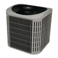
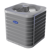
The 25TPA7 Performance™ Series 2-Stage Heat Pump with Puron Refrigerant is designed for residential heating and cooling applications, available in 2 to 5 tons capacity. This unit is engineered for efficiency and reliability, utilizing Puron (R-410A) refrigerant, which is an environmentally friendly alternative.
This heat pump operates in two stages for both heating and cooling, allowing for more precise temperature control and enhanced energy efficiency compared to single-stage units. In cooling mode, it extracts heat from the indoor air and transfers it outdoors. In heating mode, it reverses the process, extracting heat from the outdoor air and transferring it indoors. The 2-stage operation means the compressor can run at a lower capacity (approximately 67%) during mild conditions and switch to full capacity (100%) during more extreme temperatures, optimizing comfort and reducing energy consumption.
The unit is equipped with a defrost control system that prevents ice buildup on the outdoor coil during heating operation in cold weather. This control is time/temperature based, with field-selectable settings for defrost intervals (30, 60, 90, or 120 minutes, factory set to 60 minutes). The defrost cycle is initiated when the coil temperature reaches approximately 32°F (0°C) and terminates when the defrost thermostat opens or automatically after 10 minutes. A "Quiet Shift-2" feature, which is field-selectable, reduces noise during defrost and heating cycle restarts by temporarily de-energizing the compressor and reversing valve.
The 25TPA7 is designed to be connected to a factory-approved indoor unit, such as an ECM furnace or variable speed furnace, to form a complete HVAC system. The indoor unit's blower operation is matched to the compressor's capacity stages, allowing for optimal airflow during high and low-stage cooling.