EasyManua.ls Logo

Carrier Infinity 25HNB6 User Manual

Carrier Infinity 25HNB6
16 pages
To Next Page IconTo Next Page
Page #1 background imageLoading...
Page #1 background image
25HNB6(2to5Tons)
25HNB9(2to5Tons)
Infinityr 2 --- S t a g e H e a t P u m p
with Puronr Refrigerant
Installation Instructions
SAFETY CONSIDERATIONS
Improper installation, adjustment, alteration, service, maintenance,
or use can cause explosion, fire, electrical shock, or other
conditions which may cause death, personal injury, or property
damage. Consult a qualified installer, service agency, or your
distributor or branch for information or assistance. The qualified
installer or agency must use factory--authorized kits or accessories
when modifying this product. Refer to the individual instructions
packaged with the kits or accessories when installing.
Follow all safety codes. Wear safety glasses, protective clothing,
and work gloves. Use quenching cloth for brazing operations.
Have fire extinguisher available. Read these instructions
thoroughly and follow all warnings or cautions included in
literature and attached to the unit. Consult local building codes and
current editions of the National Electrical Code ( NEC ) NFPA 70.
In Canada, refer to current editions of the Canadian electrical code
CSA 22.1.
Recognize safety information. This is the safety--alert symbol
!
!
When you see this symbol on the unit and in instructions or
manuals, be alert to the potential for personal injury. Understand
these signal words; DANGER, WARNING, and CAUTION. These
words are used with the safety--alert symbol. DANGER identifies
the most serious hazards which will result in severe personal injury
or death. WARNING signifies hazards which could result in
personal injury or death. CAUTION is used to identify unsafe
practices which would result in minor personal injury or product
and property damage. NOTE is used to highlight suggestions
which will result in enhanced installation, reliability, or operation.
!
WARNING
ELECTRICAL SHOCK HAZARD
Failure to follow this warning could result in personal injury
or death.
Before installing, modifying, or servicing system, main
electrical disconnect switch must be in the OFF position and
install a lockout tag. There may be more than 1 disconnect
switch. Lock out and tag switch with a suitable warning label.
CUT HAZARD
Failure to follow this caution may result in personal injury.
Sheet metal parts may have sharp edges or burrs. Use care and
wear appropriate protective clothing and gloves when
handling parts.
CAUTION
!
Indoor Thermostat Control Options
Model
Infinity
Control
Standard
2 --- s t a g e
Thermostat
25HNB6 / 25HNB9 Yes Yes
INSTALLATION RECOMMENDATIONS
NOTE: In some cases noise in the living area has been traced to
gas pulsations from improper installation of equipment.
1. Locate unit away from windows, patios, decks, etc. where
unit operation sound may disturb customer.
2. Ensure that vapor and liquid tube diameters are appropriate
for unit capacity.
3. Run refrigerant tubes as directly as possible by avoiding un-
necessary turns and bends.
4. Leave some slack between structure and unit to absorb vi-
bration.
5. When passing refrigerant tubes through the wall, seal open-
ing with RTV or other pliable silicon--based caulk. (See Fig.
1.)
6. Avoid direct tubing contact with water pipes, duct work,
floor joists, wall studs, floors, and walls.
7. Do not suspend refrigerant tubing from joists and studs with
a rigid wire or strap which comes in direct contact with
tubing.(See Fig. 1.)
8. Ensure that tubing insulation is pliable and completely sur-
rounds vapor tube.
9. When necessary, use hanger straps which are 1 in. wide and
conform to shape of tubing insulation. (See Fig. 1.)
10. Isolate hanger straps from insulation by using metal sleeves
bent to conform to shape of insulation.
When outdoor unit is connected to factory--approved indoor unit,
outdoor unit contains system refrigerant charge for operation with
AHRI rated indoor unit when connected by 15 ft. (4.57 m) of
field--supplied or factory accessory tubing. For proper unit
operation, check refrigerant charge using charging information
located on control box cover and/or in the Check Charge section of
this instruction.
IMPORTANT: Maximum liquid--line size is 3/8--in. OD for all
residential applications including long line applications.
IMPORTANT: Always install the factory--supplied liquid--line
filter drier. Obtain replacement filter driers from your distributor or
branch.

Other manuals for Carrier Infinity 25HNB6

Question and Answer IconNeed help?

Do you have a question about the Carrier Infinity 25HNB6 and is the answer not in the manual?

Carrier Infinity 25HNB6 Specifications

General IconGeneral
BrandCarrier
ModelInfinity 25HNB6
CategoryHeat Pump
LanguageEnglish

Summary

Safety Considerations

Recognize Safety Information

Understanding safety symbols and signal words for hazard awareness.

Electrical Shock Hazard

Warning about severe injury or death from electrical hazards during installation.

Cut Hazard

Caution concerning sharp edges on sheet metal parts causing potential injury.

Unit Mounting and Clearances

Install on a Solid, Level Mounting Pad

Guidelines for securing the unit to a stable, level mounting pad.

Clearance Requirements

Specifications for maintaining adequate space around the unit for airflow and service access.

Piping and System Connections

Elevate Unit

Instructions for elevating the unit to ensure drainage and clearance above snowfall.

Long-Line Refrigerant Applications

Requirements for installing solenoid valves in long-line refrigerant piping.

Make Piping Connections

Procedures for connecting refrigerant lines, including crucial safety warnings.

Refrigerant System Components

Install Liquid-Line Filter Drier

Procedure for correctly installing the required liquid-line filter drier.

Outdoor Refrigerant Connections

Steps for connecting refrigerant tubing to the outdoor unit and adapter tubes.

Evacuation Procedures

Methods for deep vacuum or triple evacuation to remove air from the system.

Electrical and Control Wiring

Make Electrical Connections

Guidelines for safe routing and connecting power and ground wires.

Connect Control Wiring

Instructions for connecting low-voltage control wires to the unit's control board.

Final Wiring Checks

Verifying secure wiring terminations and proper routing for reliability.

System Start-Up and Airflow

Start-Up Procedures

Essential steps for safely initiating system operation after installation.

Airflow Configuration

Adjusting fan speeds for optimal airflow based on system configuration.

Operational Features and Timing

Crankcase Heater Operation

How the crankcase heater functions to protect the compressor in cold conditions.

Outdoor Fan Motor Operation

Explanation of the outdoor fan's behavior during various operating modes.

Time Delays

Overview of system time delays for protection and staging.

Low Ambient Cooling and Defrost

Infinity Controlled Low Ambient Cooling

How the Infinity Control enables low ambient cooling operation without a kit.

Defrost Cycle Operation

Details on defrost intervals, initiation conditions, and termination criteria.

System Charging and Maintenance Checks

Check System Charge

Procedures for verifying and adjusting refrigerant charge for optimal performance.

Heating Check Chart Procedure

Using charts to check system operation and refrigerant charge in heating mode.

Major Components and Troubleshooting

Major Components Overview

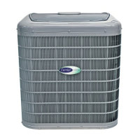
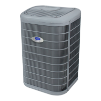
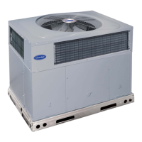
Description of key components like control boards, compressors, and contactors.

Troubleshooting System Communication

Diagnosing issues related to communication failures between system components.

Pressure Switch Protection

How high and low-pressure switches protect the system from abnormal pressures.

Advanced System Diagnostics

Compressor Voltage Sensing

Monitoring compressor voltage for proper operation and potential faults.

Unloader Test Procedure

Methods to test the compressor's unloader mechanism for proper staging.

Temperature Thermistors

Understanding thermistor function and resistance values for temperature sensing.

Fault Detection and Status Codes

Failed Thermistor Default Operation

System behavior when outdoor air or coil thermistors fail.

Status Codes Interpretation

How to read and interpret amber LED status codes for diagnosing system faults.

Related product manuals