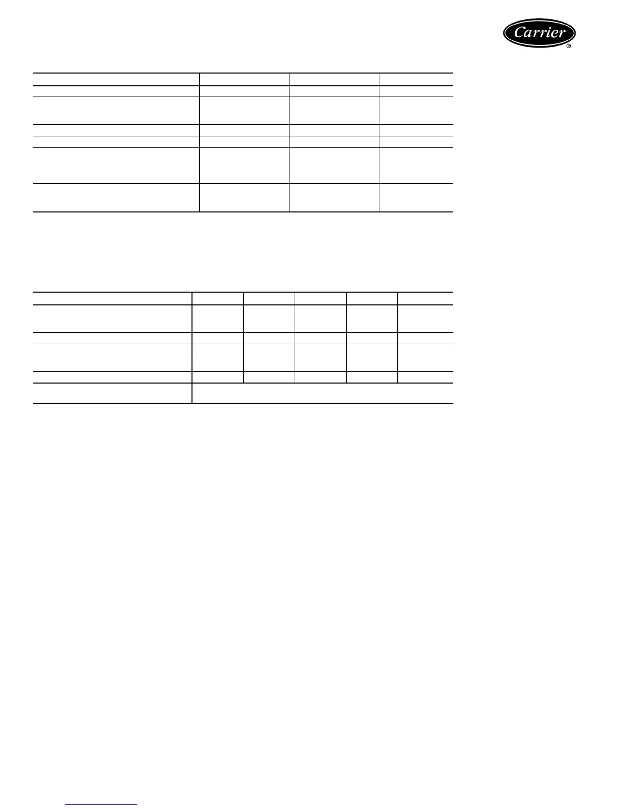
Physical data — SI (cont)
COOLER
30HR,HS SIZE 070,080,090 100,110,120 140,160
COOLER PART NO. 40HA401--- 664 684 704
DIMENSIONS
OD (mm) 324 406 406
Length (mm)* 2057 2108 2743
NET WATER VOLUME (L)† 82.1 152.9 198.3
REFRIGERANT CIRCUITS 222
MAXIMUM DESIGN WORKING
PRESSURE (kPa)
Refrigerant Side 1620 1620 1620
Fluid (Shell) Side 2068 2068 2068
FLUID CONN. (in.)
Inlet and Outlet 4** 5** 6**
Drain
3
⁄
4
FPT
3
⁄
4
MPT
3
⁄
4
MPT
*Between tube sheets.
†Includes nozzles.
**Victaulic-type water connections.
CONDENSER
CONDENSER PART NO. 09RP--- 033 043 054 070 084
DIMENSIONS
OD (mm) 273 324 324 324 356
Length (mm)* 1715 1956 2118 2419 2108
NET FLUID VOLUME (L) 21.6 32.2 37.5 43.1 51.9
FLUID CONN. — in. diameter†
Inlet IPS** 2
1
⁄
2
3332
1
⁄
2
††
Outlet IPS** 2
1
⁄
2
333 4
FLUID PASSES 33333or6
MAXIMUM DESIGN WORKING Refrigerant Side — 2654
PRESSURE (kPa) Fluid Side — 1724
LEGEND
IPS — Iron Pipe Size
OD — Outside Diameter
*Between tube sheets.
†On part no. 084 condensers, data is for 3-pass only. For 6-pass, inlet and outlet connections are 2
1
⁄
2
inches.
**Field welded (flange with weld stub provided for all connections).
††The 09RP084 has 2 inlet connections.
NOTES:
1. The 2
1
⁄
2
-in. and 3-in. condenser connections are equipped with slip-on flanges bolted to the condensers and
designed for field welding of field-supplied 2
1
⁄
2
-in. and 3-in. schedule 40 pipe.
The 4-in. condenser connections are equipped with welding neck flanges bolted to the condensers and designed
for field welding of field-supplied 4-in. schedule 40 pipe.
2. Standard 30HR,HS160 unit is supplied with 3-pass condensers. To convert from 3 to 6 pass, proceed as follows:
a. Remove 4-in. outlet flanges.
b. Cover 4-in. (09RP084) 3-pass condenser fluid outlet with blind flanges (field supplied).
3. Water outlet and inlet connections are rated according to ANSI/ASME B 16.5 (American National Standards
Institute/American Society of Mechanical Engineers) latest revision.
8
 Loading...


