GB - 1
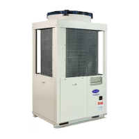
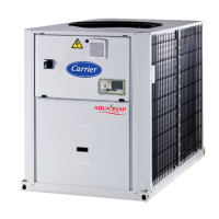
30RB/30RQ
Air-cooled liquid chillers and reversible air-to-water heat pumps with
integrated hydronic module
ENGLISH
For the use of the control system, refer to the Pro-Dialog + control manual.
Contents
Page
Physical data ........................................................................................................................................................................ 2/3
Electrical data ..................................................................................................................................................................... 2/3
Dimensions and location of hydraulic connections ................................................................................................. 4
User interface and main switch ...................................................................................................................................... 5
Clearance for horizontal outlet unit ............................................................................................................................. 5
Clearance for vertical outlet unit .................................................................................................................................... 5
General information and hydronic module .............................................................................................................. 6/7
Water connections ............................................................................................................................................................ 7/9
Electrical connections ....................................................................................................................................................... 10
Refrigerant charge ............................................................................................................................................................. 10/11
Electronic control ............................................................................................................................................................... 11
Start-up ................................................................................................................................................................................. 12
Compressor replacement................................................................................................................................................. 12
Pump replacement ............................................................................................................................................................ 12
Unit protection devices .................................................................................................................................................... 12/13
Operating limits and operating range .......................................................................................................................... 13
General maintenance ........................................................................................................................................................ 14
Maintenance ....................................................................................................................................................................... 14
Final recommendations .................................................................................................................................................... 14
Troubleshooting ................................................................................................................................................................. 15
Start-up check list
_________________________Start up date
Equipment sold by: _________________________________________________ Contract No: _________________________________
Installed by: _______________________________________________________ Contract No: _________________________________
Site address ____________________________________________________________________________________________________
Equipment type and serial No: 30RB ___________________________________________________________________
30RQ ___________________________________________________________________
ELECTRICAL DATA:
Supply voltage Ph 1: _______________V Ph 2: _______________V Ph 3: _______________V
Nominal voltage: _________________________________________ V % network voltage ____________________________
Current draw Ph 1: _______________A Ph 2: _______________A Ph 3: _________________A
Control circuit voltage: _____________________________________ V Control circuit fuse__________________________A
Main circuit breaker rating ________________________________________________________________________________________
PHYSICAL DATA:
Coil: Plate heat exchanger:
Entering air temp.: ____________________________°C Entering water temp.: _____________________ °C
Leaving air temp.: ____________________________°C Leaving water temp.: ______________________ °C
Pressure drop (water): _____________________ kPa
SAFETY DEVICE SETTING:
High pressure switch: cut-out: _________________kPa cut-in: ________________________ kPa
Oil level _______________________________________________________________________________________________________
OPTIONS:
Commissioning engineer (name) __________________________________________________________________________________
Customer agreement
Name:______________________________________ Date: ___________________________________
Note: Complete this start-up list at the time of installation


 Loading...