3. Attach the
5
⁄
32
-in. ID Tygon tubing to the appropriate port,
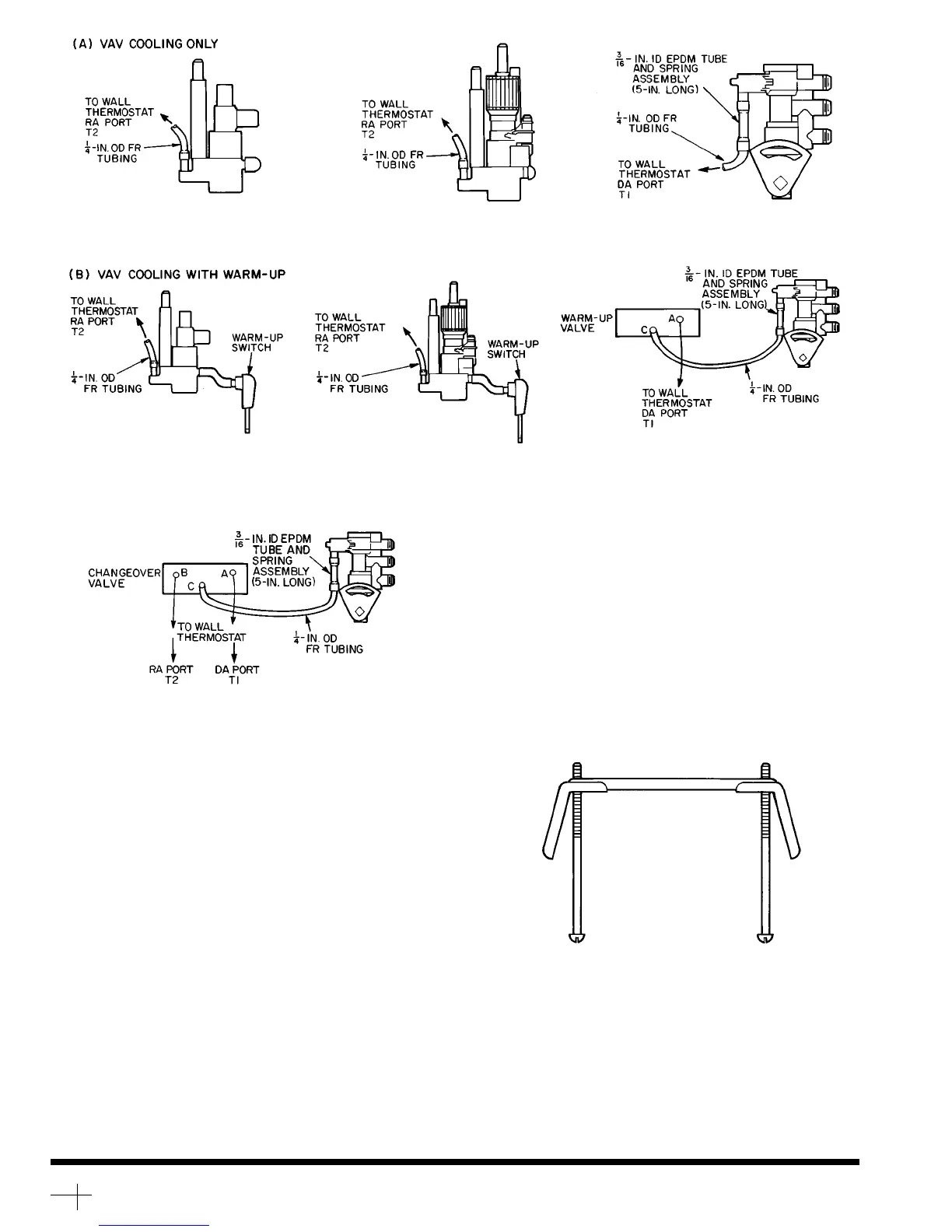
T1 or T2, as shown in Fig. 2. Attach the adaptor to the
1
⁄
4
-in. OD FR tubing. Connect the other end of the tubing
to the unit volume control (purchased separately).
NOTE: A 5-in. long,
3
⁄
16
-in. ID EPDM tube and spring
assembly is included in the thermostat package for con-
necting the
1
⁄
4
-in. FR tubing to the 37C or 37HS volume
control.
4. Mount the thermostat onto the junction box, being care-
ful not to allow tubing to kink. Attach the thermostat to
the junction box using the screws provided. Replace cover.
5. For mounting applications without a junction box, use toggle
bolt assembly as shown in Fig. 3. Package 37HS900019
contains this toggle bolt assembly.
NOTE: Control components shown above must be purchased sepa-
rately. Consult Carrier dealer for package numbers. Refer to specific
package installation instructions for mounting details.
The
3
⁄
16
-in. ID EPDM tubing with spring is supplied with the wall
thermostat.
Fig. 2 — Connecting Tubing to Unit Volume Control
35BB,BC UNITS
(SYSTEM POWERED)
37AG,AH,AJ UNITS 37CL,CM,CN UNITS
37HS UNITS
35BB,BC UNITS
(SYSTEM POWERED)
37AG,AH,AJ UNITS 37CL,CM,CN UNITS
37HS UNITS
(C) VAV COOLING/VAV HEATING - 37CL,CM,CN, 37HS UNITS ONLY
(NOTE: MAX DUCT TEMPERATURE 120 F)
Fig.3—Toggle Bolt Assembly for Mounting
Applications Without Junction Box
Copyright 1991 Carrier Corporation
Manufacturer reserves the right to discontinue, or change at any time, specifications or designs without notice and without incurring obligations.
Book 3
Tab 6a
PC 201 Catalog No. 533-715 Printed in U.S.A. Form 37HS-5SI Pg 2 7-91 Replaces: 37C-5SI